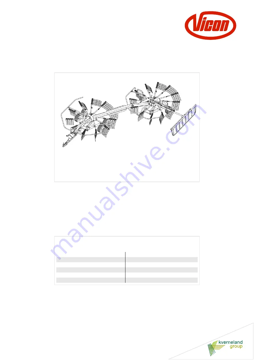
Andex 714 T Vario
Andex 714 T Evo
Assembly instructions
Original assembly instructions
Edition
06.2012
Date of print
04.2013
Language
EN
Machine number
VF69621551 – / VF69626651 –
Model
VF6962
Document number
VF16648691.EN
Page 1: ...14 T Vario Andex 714 T Evo Assembly instructions Original assembly instructions Edition 06 2012 Date of print 04 2013 Language EN Machine number VF69621551 VF69626651 Model VF6962 Document number VF16648691 EN ...
Page 2: ...up Gottmadingen N V Germany Reproduction transfer to other media translation or the use of extracts or parts of this manual without the explicit permission of Kverneland is not permitted All rights reserved The contents of this operating manual are subject to change without notice The right to technical revision is reserved ...
Page 3: ...ssembly 15 Fitting the central beam 18 Fitting the front rotary assembly 19 Connecting the hydraulics 22 Pilotbox hydraulic diagram 24 Fitting the tine arm 25 Fitting the rear guard bars 26 Fitting the front guard bars 27 Fitting the swath former 28 Fitting the PTO shaft 29 Pallet packaging 30 Requirements 30 Preparing the rear rotary assembly 31 Preparing the front rotary assembly 32 Further asse...
Page 4: ...ou must familiarise yourself with the contents of these assembly instructions before assembly or operating the machine In this way you will achieve optimum work results and operational safety The assembly instructions form an integral part of the machine and must always be kept to hand This will allow Accidents to be avoided Warranty conditions to be met For the employer Untrained or unauthorised ...
Page 5: ... information The Examples pictogram indicates examples that assist under standing of the instructions The spanner indicates tips for assembly or adjustment work This arrow in the diagram shows the direction of travel The brush indicates the points that must be lubricated using the brush The grease gun indicates the points that must be lubricated using the grease gun Switch on the tractor Secure th...
Page 6: ...ughly read and observed It is the responsibility of the operator to ensure that all personnel involved in the assembly are provided with the relevant accident prevention regulations as well as generally applicable health and safety and road safety regulations All personnel involved in the assembly must be aware of these rules and regulations and adhere to them they must also be instructed on the p...
Page 7: ... the instructions A part conforms to the requirements only if it is an original part or if it is expressly approved by the manufacturer Hazard areas Do not leave the engine running in enclosed spaces Actuation elements cables chains and rod assemblies of remotely controlled equipment must be fitted in such a way that they cannot cause unintended movement in any transport or work position All tight...
Page 8: ...h the table below should no other torques be specified The torque specifications refer to a dry coefficient of friction 0 12 Tighten safety bolts and lock nuts to a 10 higher value Observe the torque specifications Securely tighten screws nuts and bolts to the specified torques Incorrectly tightened screwed connections can loosen or become jammed This could result in machine damage or injury Bolt ...
Page 9: ...Safety 9 Special tightening torques Observe the special tightening torques for the following screwed con nections 90 Nm spring tine 20 Nm rotor chassis wheel nuts Spring tines 90 Nm 20 Nm wheel nut M12 ...
Page 10: ...ws Rotary direction right clockwise Rotary direction left anticlockwise Rotation about a vertical axis viewed from top to bottom Rotation about a horizontal axis viewed at right angles to the direction of travel from left to right The rotation of bolts and nuts etc is always viewed from the operating side Front Left Right Rear Top Bottom Rotary direction right ...
Page 11: ... components Front frame Support wheel Drawbar cylinder Chassis cylinder PTO shaft Articulated arm Centre frame Swath former Rear frame Tine arm Rotor Tine supports Guard bar Slewing gear Spare wheel Steering cylinder Tandem axle Drawbar ...
Page 12: ...h former Centre frame PTO shaft with overload clutch No Assembly group Page 1 Fitting the rear rotary assembly 15 2 Fitting the central beam 18 3 Fitting the front rotary assembly 19 4 Fitting the tine arm 25 5 Fitting the rear guard bars 26 6 Fitting the front guard bars 27 Fitting the swath former 28 Fitting the PTO shaft 29 ...
Page 13: ... The drawbar is swivelled into the correct position on the front rotary assembly and fitted The two rotary assemblies are then connected to one another Note the relevant chapter under the heading Crate packaging Quick Set packing With the Quick Set packing the machine is ready to use once the tine supports are fitted and the basic settings and final tasks have been carried out See Final tasks page...
Page 14: ...e REPORT MISSING PARTS form and send it to the ORDER DESK in Kerteminde straight away Removing the surface protection Remove the surface protection e g Tectyl with which the bare surfaces such as tine arms tine supports and bearing shafts have been coated Grease the bare surfaces using a brush Observe the safety information Observe the safety information when carrying out all work Disregard for sa...
Page 15: ...ase the fastenings wires lashing straps and take the rear rotary assembly out of the crate Note the attachment points See adjacent illustration and stickers on the machine Place the rear rotary assembly securely on stands Attachment points Attachment points ...
Page 16: ... running wheels to the single axle Observe the torque setting Observe the specified torque of 20 Nm when tightening the wheel nut Higher tightening torques will damage the plastic washer No Quantity Part 1 2 Wheels 2 2 Assembly material for wheels 20 Nm Note the sequence of assembly ...
Page 17: ...nd the rear rotary assembly on the chassis Secure the rear rotary assembly against rolling away and place the support on a stand Observe the torque setting Observe the specified torque of 20 Nm when tightening the wheel nut Higher tightening torques will damage the plastic washer 20 Nm Plastic washer No Quantity Part 1 2 Tandem axles 2 6 Wheels 3 8 Assembly material for wheels No Quantity Part 1 4...
Page 18: ... on the central beam This side is not locked Connect the rear rotary assembly and central beam using bolts and nuts For the optional additional swath former fit the transport holder behind the flange piece on the rear rotary assembly Fit the transport holder using M16 x 65 bolts Fit the T bolt with plate to the transport holder See Fitting the transport holder for the additional swath former page ...
Page 19: ...al beam Use suitable lifting gear to bring the front rotary assembly to the central beam Fit the front rotary assembly to the central beam with a pin dia 35 and secure with a dowel pin Fit the second pin dia 25 onto the central beam and secure with a washer and split pin Route the hydraulic hoses and cables underneath the cover Fasten the cover using a bolt Guide the hydraulic hoses and cables thr...
Page 20: ...support wheel as follows Fit the preassembled support wheel on the right of the front rotary assembly Secure the preassembled support wheel with a pin and safety splint Fit the spring as shown in the adjacent illustration In the EVO version the support wheel is optional In the VARIO version the support wheel is included in the standard equipment Support wheel fitted on the left Support wheel fitte...
Page 21: ... parking stand The parking stand is attached on the left Fit the parking stand as follows Fit the preassembled parking stand on the left of the front rotary assembly Secure the preassembled support wheel with a pin and safety splint ...
Page 22: ...the hydraulics EVO hydraulic diagram with 3 way ball valve 3 way ball valve Drawbar cylinder Front chassis cylinder Rear chassis cylinder Swath former cylinder Rear steering cylinder Control cable Hose labelling 5 2 4 1 5 5 5 2 1 4 ...
Page 23: ...ging 23 Hydraulic diagram for the VARIO with pilotbox Drawbar cylinder Front chassis cylinder Rear chassis cylinder Swath former cylinder Rear steering cylinder Front steering cylinder Pilotbox 5 2 1 4 3 4 5 5 2 4 ...
Page 24: ...Crate packaging 24 Pilotbox hydraulic diagram Pilotbox Plug for the power supply Hydraulic block ...
Page 25: ...Nm Tighten the tine arm fixing bolt to 110 Nm No Quantity Part 1 23 Tine arms 2 23 M12 x 60 bolts clamping bolt 3 46 M12 washers 4 46 M12 self locking nuts 5 23 M12 x 75 bolts fixing bolt 6 46 Shims 7 23 35 x 52 x 3 5 washer disc Tine arm Shim M12 self locking nut 90 Nm M12 self locking nut 120 Nm M12 washer 35 x 52 x 3 5 washer disc M12 x 75 fixing bolt M12 x 60 clamping bolt Rotor gear Shim M12 ...
Page 26: ... the right guard bar through the lowermost hole and secure Connect the cables for the lighting equipment Please observe the illustrations in the spare part manual Fit the holders for the wheel chocks Fit the reflector onto the guard bar Fit the guard bars correctly Make sure that you fit the guard bars correctly If fitted incorrectly guard bars may cause damage to the machine Support arm Warning s...
Page 27: ...ft guard bar through the uppermost hole and secure Insert the right guard bar through the lowermost hole and secure Fit the guard bars correctly Make sure that you fit the guard bars correctly If fitted incorrectly guard bars may cause damage to the machine Right guard bar Left guard bar Front rotary assembly Guard bar carrier Left guard bar Right guard bar ...
Page 28: ...8 Fitting the swath former Insert the preassembled swath former into the swath former carrier and secure with both T bolts Swath former Swath former carrier T bolt T bolt Fit the swath former into the front hole pattern ...
Page 29: ...d cone a Turn the guard cone a and tube b until the noses of the slide ring d are above the slots in the guard cone arrows Push back the guard cone and tube Push the single joint e onto the PTO stub shaft Ensure that it is securely engaged f Re secure the PTO shaft guard in the reverse sequence Overload clutch Fit the PTO shaft with overload clutch PTO shaft Overload clutch ...
Page 30: ...he REPORT MISSING PARTS form and send it to the ORDER DESK in Kerteminde straight away Removing the surface protection Remove the surface protection e g Tectyl with which the bare surfaces such as tine arms tine supports and bearing shafts have been coated Grease the bare surfaces using a brush Observe the safety information Observe the safety information when carrying out all work Disregard for s...
Page 31: ...ing accessories and set down for further assembly Note the relevant chapter under the heading Crate packaging Secure the rear rotary assembly using suitable lifting accessories and be aware of the limit stops Remove the transport locking devices Place the rear rotary assembly on stands Rear rotary assembly Front rotary assembly Transport locking device Transport locking device ...
Page 32: ...d guide the drawbar cylinder to the retainer on the main frame Fit the spring on the right hand side Insert the pin on the left hand side through the retainer and secure on the inside with a dowel pin Further assembly steps To carry out further assembly steps proceed as follows See Fitting the central beam page 18 See Connecting the front rotary assembly to the central beam page 19 See Connecting ...
Page 33: ...17 Fit the contact roller axle to the contact roller holder using retainers Fit the contact rollers Adjusting the contact rollers Slightly loosen the bolts on the two retainers Set the contact roller axle to a height of H 35 mm Tighten and secure the bolts on both retainers Contact roller mount Contact roller axle Contact roller mount Contact roller axle Contact roller 35 mm ...
Page 34: ...Additional swath former The parts illustrated are included in the scope of delivery for the optional additional swath former A Transport holder for the additional swath former C Support for the additional swath former D T bolt ...
Page 35: ...itional swath former C onto the guard bar carrier Fit the transport holder A for the additional swath former onto the main frame flange B between the central beam and rear rotary assembly Push in the additional swath former and secure it with T bolts D T bolt Support Guard bar Front rotary assembly Additional swath former Hole pattern Carrier for the guard bar T bolt Direction of travel Support fo...
Page 36: ...nd the flange plate on the rear rotor See Fitting the central beam page 18 Fitting the additional swath former to the support Fit the additional swath former to the support Transport holder T bolt Flange plate B Transport holder for the additional swath former Direction of travel Support for additional swath former Additional swath former Washer ...
Page 37: ...t the cable connectors securely PTO shaft connections engaged Check the lighting equipment Check the air pressure 1 5 bar Trial run To fill the hydraulic system requires about 3 litres of hydraulic oil SAE 90 API GL4 Operate all hydraulic functions of the machine ten times to their end stops in order to remove any air from the system Upon completion of the trial run check the hydraulic system for ...