background image

29

GT ULTRA ZERO AIR GENERATOR

USER MANUAL

www.vicidbs.com

Version 1.03.0000

10. FLUIDICS DIAGRAM

System:

Schematic no:

Date:

Created:

Checked:

Released:

THIS DOCUMENT AND THE INFORMATION WHICH

IT CONTAINS SHALL NOT BE USED, EXPLOITED

OR SOLD, AND SHALL NOT BE REVEALED OR

DISCLOSED TO OTHERS WITHOUT THE EXPRESS

WRITTEN PERMISSION OF VICI. THIS DOCUMENT

SHALL REMAIN THE PROPERTY OF VICI AND

SHALL BE RETURNED UPON DEMAND.

R

 Rev.:

Sheet:

By:

Description:

ECN no:

GT Plus
air flow diagram

13.05.2020

14.05.2020

SBU

SB

1

1/1

Summary of Contents for GT Plus 1500

Page 1: ...ion 1 03 0000 APPLICABLE MODELS This manual is applicable to the following models GC Plus 1500 GC Plus 3000 GC Plus 6000 GC Plus 15000 GC Plus 30000 Version 1 03 0000 GT ULTRA ZERO AIR GENERATOR USER...

Page 2: ...andard Shipping 13 6 2 UNPACK UNIT AND OPEN COVER 13 6 3 INSTALL 1 4 EXTERNAL INLET FILTER 13 6 4 CHECK VOLTAGE SETTING 13 6 5 UNIT POSITIONING 14 6 6 CONNECT AIR SUPPLY 15 6 7 CONNECT OUTPUT 15 6 8 L...

Page 3: ...Year Catalyst Replacement Kit 21 8 2 FILTER REPLACEMENT 22 8 2 1 Annual Pre filter Element Replacement 22 8 2 2 Annual High Grade In Line Particulate Filter Replacement 23 8 2 3 Three Year Catalyst Ch...

Page 4: ...y eliminating the need for inconvenient high pressure gas cylinders Eliminating gas cylinders reduces operating costs associated with materials labor and down time The GT Ultra Zero Air generator will...

Page 5: ...ness or operator action in order to avoid undesirable consequences The manual must be consulted in all cases where this symbol is marked on the device Risk of asphyxia Caution is necessary when operat...

Page 6: ...romised or void 3 2 Instrument Safety Instructions Read all instructions ALWAYS WEAR SAFETY GLASSES when working with this equipment Everyday eye glasses have only impact resistant lenses They are NOT...

Page 7: ...s 1 2 1 Max HC in 100 ppm Max CO in 50 ppm Technology Platinum catalyst LED indicators Power on off system ready errors Warm up time minutes 45 Electrical supply 110 120V 60Hz 220 240V 50Hz Power cons...

Page 8: ...ntrol board will illuminate the yellow external LED and close the outlet valve disabling the system Stage 2 Air Dryer Air is next passed into a dual column pressure swing adsorption air dryer to remov...

Page 9: ...A final high grade filter is used to remove 99 99 of particulates greater than 0 5 microns in size This will ensure that no harmful particles will be able to enter your analyzer Outlet Solenoid valve...

Page 10: ...ULTRA ZERO AIR GENERATOR USER MANUAL www vicidbs com Version 1 03 0000 5 1 FUNCTIONALITY COOLING SYSTEM ZERO AIR OUTLET H2O CO2 TRAP OUTLET FILTER CATALYST COM PRESSED AIR INLET NOx SOx TRAP INLET FI...

Page 11: ...LED and the output flow is disabled 3 Monitors critical system parameters The control board serves as a QA monitor continuously checking for proper inlet pressure and catalyst temperature to ensure Ul...

Page 12: ...ly assembled and fully burned in ready for installation High quality inlet air filter to remove particles and bulk moisture from air before entering the generator 1 Power cable 2 Fuses 220 VAC 1 Insta...

Page 13: ...ll depend on the transport tubing or hose of the GC detection system or analyzer A hose clamp is recommended if flexible tubing is used 6 2 UNPACK UNIT AND OPEN COVER 6 3 INSTALL 1 4 EXTERNAL INLET FI...

Page 14: ...either side of the unit B Mounted to a wall Drill holes 200 mm 7 87 inches apart into the wall and insert the supplied mounting screws Tighten only enough so there is approximately 1 4 extruding from...

Page 15: ...e air from your GT Ultra Zero Air generator stainless steel tubing or instrument grade Teflon tubing should be used to connect the generator to the GC detection system or analyzer air inlet port Coppe...

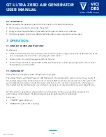
Page 16: ...ll go immediately to operation mode This quick start feature is for customer convenience when power is interrupted only for short periods and a full warm up cycle is not required Warm up cycle takes 4...

Page 17: ...m does not start the warm up cycle The processor immediately flashes the red Check System LED If the catalyst is within 2 months of expiring then the red Check System LED will flash but the system wil...

Page 18: ...t Low catalyst temperature will also prevent the unit from coming out of the warm up cycle and will result in a fault after one hour if the warm up fails 7 4 4 Catalyst Temperature High The on board t...

Page 19: ...ED The control board will continuously check whether catalyst temperature is within limits If yes other faults will be checked will go to Operation Mode if no faults are found If catalyst temperature...

Page 20: ...n performed according to instructions above 2 Supply air pressure has been shut off with an in line valve 3 Line pressure has been released with an in line relief valve 4 Unit has been shut off and is...

Page 21: ...1 Oven Catalyst 1 Cooling coil 8 1 1 Annual Maintenance Kit The GT Ultra Zero Air generator is designed to operate continuously for an entire year before service is required An annual maintenance kit...

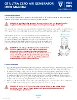
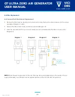
Page 22: ...r Push Unscrew Turn Pull Apart Pull and Replace Element Filter 8 2 Filter Replacement 8 2 1 Annual Pre Filter Element Replacement Remove the filter bowl by pressing on the lever and turning the bowl c...

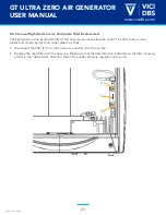
Page 23: ...the final component before the outlet The filter body is clear plastic and is held by inlet and outlet plastic air lines Disconnect the filter 1 from the push in connectors 2 of the air line Replace t...

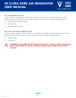
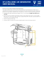
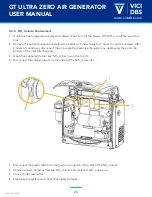
Page 24: ...nt Allow the unit to cool down for a minimum of two hours before replacement If unit has been powered recently and catalyst is hot turn off the power DO NOT turn off the air at this time Remove the ou...

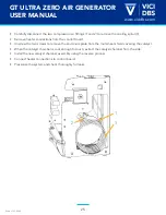
Page 25: ...ons from the control board Unscrew the two screws to remove the aluminum plate from the metal heat shield covering the catalyst When the catalyst chamber is cool enough to touch extract the catalyst c...

Page 26: ...talyst After 2 hours of cool down disconnect the air supply Depressurize the system by depressing the pin at the bottom of the inlet filter housing Open front panel with door key NOx column is on the...

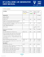
Page 27: ...stem Fault Catalyst temperature is low at the 40 min checkpoint 5 Warm up Mode 3 to 40 minutes max System Fault System is not warming up OFF OFF ON 5 System Fault Catalyst temperature is low at the 40...

Page 28: ...ION BLINKING 1 OFF Minimum Pressure Pre Alarm BLINKING 2 OFF Maximum Pressure Pre Alarm BLINKING 3 ON Valve Switching Pre Alarm BLINKING 4 BLINKING Catalyst Replacement Pre Alarm 1 ON Minimum Pressure...

Page 29: ...OCUMENT AND THE INFORMATION WHICH IT CONTAINS SHALL NOT BE USED EXPLOITED OR SOLD AND SHALL NOT BE REVEALED OR DISCLOSED TO OTHERS WITHOUT THE EXPRESS WRITTEN PERMISSION OF VICI THIS DOCUMENT SHALL RE...

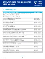
Page 30: ...up grade DB NGT000 012 Cooling coil for GC 1500 and GT 1500 stainless steel DB NGT000 025 Cooling coil for GC 15000 and GC 30000 copper 6mm DB NGT000 026 Cooling coil for GT 15000 and GT 30000 copper...

Reviews: