Page
3
of
4
In
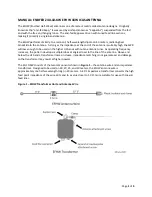
Figure 2B
(bottom), a counterpoise or ground wire (not provided) is connected to the
transformer’s
ground attachment screw. The transformer should be secured to a sturdy support. In this
configuration, a choke balun can be used at the feed point without affecting antenna performance. A
ground rod (not provided) or a counterpoise can be used but not both at the same time. The
counterpoise wire can be up to ¼-wavelength long and should be approximately under the antenna wire
with the far end unconnected. (Counterpoise length and orientation will affect SWR.)
Figure 2A (top) and 2B (bottom)
–
Typical EFHW Installations
The EFHW’s SWR will be affected by height above ground, type of ground, feed line interaction, and any
nearby conductive surfaces. Raising, lowering, or re-orienting the antenna may be enough to move the
SWR minimum point to the desired frequency. An antenna analyzer with a graphic display of SWR
versus frequency will greatly assist adjusting SWR as the antenna is moved.
You can also adjust SWR by changing the number of turns on the loading coil. Removing turns will raise
the resonant frequency. This requires removing the ring terminal (a new terminal will be required),
pulling the short end of the antenna wire through the coil form holes, unwinding the desired turns, re-
threading the wire through the coil form holes, and reattaching the wire to the antenna attachment
screw (without a terminal). When the desired SWR and frequency are achieved, attach a new ring
terminal and re-attach the wire thimble and wire clip strain relief hardware.


