


Appendix C PCIe (Slot) Configuration Procedure
PCIe Domain Configuration Overview
mA-1302/mA-1305 AXIe Chassis Operation Manual
Rev. D0
Page C-2
April 2020
PCIe Domain Configuration Overview
The CMP mA-1305 Chassis supports up to four PCIe domains, each domain with it's own
“Root”, or master device, such as a COM Express CPU or other PCIe master capable
device. Root devices MUST NOT be configured to use the same PCIe domain. If more
than one root device is assigned the same PCIe domain (“slot”), the system will not be able
to differentiate between the two root devices, preventing the Chassis from booting up,
leaving the system inoperable.
For example, an mA-3011 Dual Host Module contains two COM Express CPU modules;
each COM Express module is considered a “Root” device. Each COM Express CPU must
be assigned to a different PCIe domain. Each PCIe domain must have one and only one
Root, with zero or more Endpoints. An Endpoint may only belong to one device (e.g.,
mA-6806).
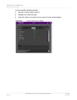
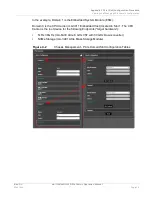
Viewing and Managing PCIe Domain Configuration
Chassis PCIe domain assignments are viewed and managed on the Chassis Management
page in the PCIe Domain panel. Press the Advanced Config button to display PCIe
Domain settings. Figure C-2 shows an example of how the PCIe Domain Advanced
Settings page will look.
The settings on this page allow users to specify one “Root” for each domain, and assign
multiple “Endpoints” to be controlled by that root. Roots and endpoints are specified by the
slot number in which the module is inserted, and the device (or “FRU”) within that slot.
For example, an mA-3011 Dual Host Module contains two CPUs, the first, or “primary”
CPU is designated “Device: 1”, and the secondary is “Device: 2”. If the mA-3011 contains
only one COM Express CPU, the CPU is identified as Device 1.
Any module without sub-sections (or “FRU” devices) has only “Device: 0”, such as the
Tx Rx 30GHz and NVMe in Figure C-2.
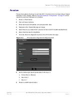
Figure C-1 shows an example of the Chassis Web UI Instrument Slot page which shows
the slot location of the modules in an mA-1305 Chassis. Figure C-2 shows an example of
the PCIe Domains configuration tables for the same system.
Figure C-1
Chassis Instrument Slot Contents
Summary of Contents for mA-1302
Page 1: ...mA 1302 mA 1305 AXIe Chassis Operation Manual ...
Page 3: ......