background image

FVAi-2030 Benchtop Microscope User Guide, 22112369-339 R000, Standard

2-7

Getting started

Navigating the Home screen

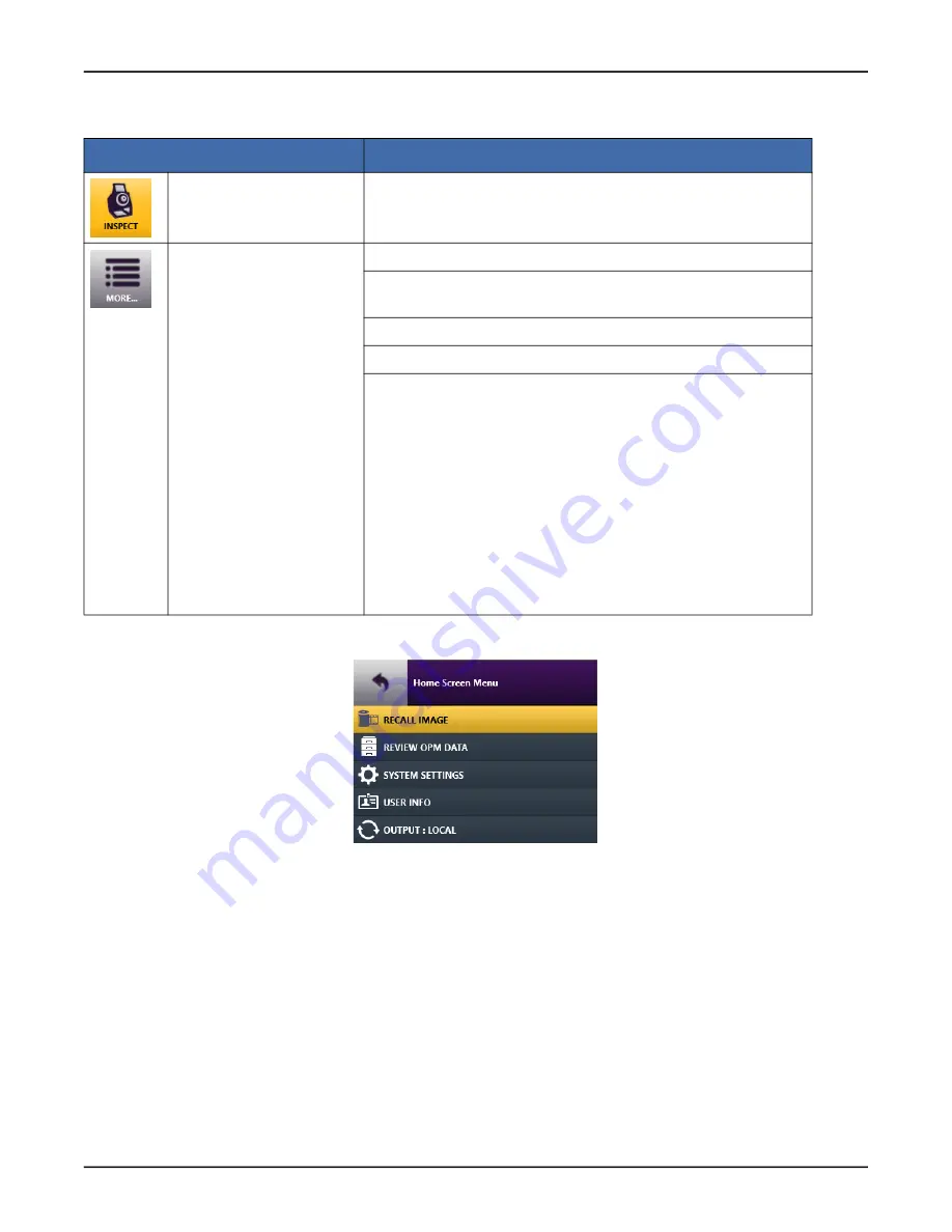
Figure 2-4: Home Screen menu example

Table 2-2: FVAi-2030 Home screen tools

Tool

Description

Inspect

 (FVAi-2030)

Activates the FVAi-2030 microscope and accesses Live view for fiber 
inspection. See 

“Accessing Live view” on page 2-8

.

More

 (Home Screen menu, 

Figure 2-4

)

RECALL IMAGE:

 See 

“Recalling test results and images” on page 3-7

REVIEW OPM DATA: 

See 

“Connecting and activating a supported USB 

device” on page 2-21

.

SYSTEM SETTINGS:

 See 

“Managing system settings” on page 2-19

USER INFO:

 See 

“Managing user information” on page 2-14

OUTPUT:

• During standalone operation, 

OUTPUT:LOCAL

 indicates local 

operation via the touchscreen.

• While the microscope is connected to an external monitor via a 

VGA connection (

OUTPUT:VGA

), and/or to FiberChekPRO via a 

USB-B connection to the computer where FiberChekPRO is 
installed, select to toggle output mode for working with the 
microscope.

Note: 

While output mode is FiberChekPRO over a USB-B connection, 

select the 

Home

 tile on the LCD touchscreen to access the 

Home


screen on the touchscreen. See


“Powering the FVAi-2030 microscope 

on or off” on page 2-3

Summary of Contents for FVAi-2030

Page 1: ...Multiple Application Platform FVAi 2030 Benchtop Microscope User Guide 22112369 339 R000 Standard December 2021 ...

Page 2: ...arising from any course of dealing usage or trade practice Under no circumstances will VIAVI be liable for any indirect or consequential damages related to breach of this warranty California Proposition 65 California Proposition 65 officially known as the Safe Drinking Water and Toxic Enforcement Act of 1986 was enacted in November 1986 with the aim of protecting individuals in the state of Califo...

Page 3: ...ǃᴹᇣ 䍘нՊਈᔲᡆ DŽ䈕ᵏ䲀н䘲 Ҿ䈨ྲ ㅹ᱃㙇 DŽ ᴹ ޣ ᑨ ᶑԦˈ䈧 㿱ӗ ᡧ DŽ ӗ ӗᰕᵏ䈧 㿱ӗ Ⲵ ṑ 䇱ҖDŽ ᴹ ǃᴹᇣ 䍘Ⲵ ර ᡰ 䜘Ԧ ᴹ ǃᴹᇣ 䍘 ݳ ݳ ಘԦ Component 䫵 Pb Hg 䭹 Cd ޝ ԧ䬜 CR6 ཊⓤ㚄㤟 PBB ཊⓤҼ㤟䟊 PBDE ӗ ѫփ Main Product ঠࡧ 䐟ᶯ㓴Ԧ PCB Assemblies X O O O O O 䜘䝽㓯 Internal wiring X O O O O O ᱮ ಘ Display X O O O O O 䭞ⴈ Keyboard O O O O O O Batteries O O O O O O Ⓚ Power Supply X O O O O O c ᐕ䴦Ԧ Electro mechanical parts X O O O O O ⴈ Hard Drive O O O O O O ݹ ඇ...

Page 4: ...stem settings 2 19 Calibrating the touchscreen 2 20 Connecting and activating a supported USB device 2 21 Activating a P5000i probe 2 21 Activating an MP Series optical power meter 2 23 3 Fiber inspection during standalone operation 3 1 Requirements for Pass Fail tests 3 2 Starting a Pass Fail test from the FVAi 2030 3 3 Viewing the fiber chamfer 3 4 Capturing images 3 5 Recalling test results and...

Page 5: ...guide provides information about the FVAi 2030 Benchtop Microscope This is the first release of this user guide For a detailed revision history see Document revision history on page D 1 To access the latest version of this user guide go to FVAi 2030 Benchtop Microscope User Guide 22112369 339 ...

Page 6: ... FVAi 2030 as a standalone device or in conjunction with the FiberChekPRO inspection and analysis software Figure 1 1 FVAi 2030 Benchtop Microscope FiberChekPRO Fiber Inspection and Analysis software Designed to operate on a PC laptop FiberChekPRO instantly captures analyzes and grades fiber end face images to determine acceptability of the end faces It identifies and characterizes defects and con...

Page 7: ...Angle FMAX SCA SL41 SC PC Duplex Fiber Microscope Adapter 30 Degree Chamfer Angle FMAX SC DUX SL30 SC PC Fiber Microscope Adapter 30 Degree Chamfer Angle FMAX SC SL30 Universal 1 25mm APC Fiber Microscope Adapter 35 Degree Chamfer Angle FMAX U12A SL35 Universal 1 25mm PC Fiber Microscope Adapter 35 Degree Chamfer Angle FMAX U12 SL35 Universal 2 5mm APC Fiber Microscope Adapter 30 Degree Chamfer An...

Page 8: ... Knowledge Base Technical Assistance Center and Knowledge Base To find the Technical Assistance Center phone number and email in your region for the FVAi 2030 Benchtop Microscope or to search the VIAVI Solutions Knowledge Base visit the VIAVI Solutions Technical Product Support site at support viavisolutions com ...

Page 9: ...ng fiber adapters and connectors on page 2 4 Navigating the Home screen on page 2 6 Accessing Live view on page 2 8 Applying a profile and an optical setting on page 2 10 Managing groups on page 2 12 Managing user information on page 2 14 Managing microscope settings on page 2 15 Managing image save options on page 2 18 Managing system settings on page 2 19 Connecting and activating a supported US...

Page 10: ...VAi 2030 microscope on or off on page 2 3 Power adapter receptacle USB B Interface 1x for connecting the FVAi 2030 microscope to a computer for use with FiberChekPRO inspection software See Using the FVAi 2030 microscope with FiberChekPRO on page 4 1 USB Interfaces 2x for connecting supported USB devices to FVAi 2030 microscope See Connecting and activating a supported USB device on page 2 21 VGA ...

Page 11: ...he rear panel of the microscope and then to the power source Step 3 Set the power switch on the rear panel to the ON position The LCD touchscreen initializes If the microscope is not connected to a computer via a USB B connection see Features on page 2 2 the Home screen appears If the microscope is connected to a computer via a USB B connection select the Home tile to access the Home screen For mo...

Page 12: ... fiber adapter onto the mount and finger tighten the adapter to secure it Do not over tighten the adapter Step 3 Power on the microscope and access Live view on the LCD touchscreen see Accessing Live view on page 2 8 Step 4 Clean the fiber connector to be inspected Step 5 Ensure that the fiber connector is correctly oriented and then insert it into the fiber adapter Step 6 Ensure that the fiber en...

Page 13: ...ring Limit setting and marker as a reference for the adjustment For information see Managing the Fiber Centering Limit setting and marker on page 2 16 Insert the end of the M5 hex screwdriver into an adjustment pilot hole until it engages and then carefully turn the screwdriver in either direction referring to the touchscreen as the position of the lens changes End CAUTION Use only the M5 hex scre...

Page 14: ...active areas of the touchscreen See Calibrating the touchscreen on page 2 20 for information Figure 2 2 FVAi 2030 Home screen Note If supported devices such as a P5000i Digital Analysis Probe and or an MP Series Optical Power Meter are connected to the microscope via a USB connection see Features on page 2 2 a tile for activating the supported device appears on the Home screen Select the tile for ...

Page 15: ...rted USB device on page 2 21 SYSTEM SETTINGS See Managing system settings on page 2 19 USER INFO See Managing user information on page 2 14 OUTPUT During standalone operation OUTPUT LOCAL indicates local operation via the touchscreen While the microscope is connected to an external monitor via a VGA connection OUTPUT VGA and or to FiberChekPRO via a USB B connection to the computer where FiberChek...

Page 16: ... the touchscreen to access the Live view tools and then select a tool Live View Tool Description Home Return to the Home screen see Navigating the Home screen on page 2 6 Magnification High Low Increase or decrease magnification of the image displayed on the touchscreen Start Test See Starting a Pass Fail test from the FVAi 2030 on page 3 3 Note For information about starting a Pass Fail test with...

Page 17: ...roups on page 2 12 RECALL IMAGE1 See Recalling test results and images on page 3 7 USER INFO1 See Managing user information on page 2 14 MICROSCOPE SETTINGS See Managing microscope settings on page 2 15 IMAGE SAVE OPTIONS See Managing image save options on page 2 18 SYSTEM SETTINGS1 See Managing system settings on page 2 19 OUTPUT LOCAL1 See Navigating the Home screen on page 2 6 Capture See Captu...

Page 18: ... You can also manage factory set and custom profiles and optical settings with FiberChekPRO making them available on or removing them from the microscope as required For information including information about applying profiles and optical settings using FiberChekPRO see the FiberChekPRO Automated Fiber Inspection and Analysis Software User Manual Step 1 In Live view select Inspection Settings and...

Page 19: ...ofile and an optical setting Select OPTICAL SETTINGS to access the optical settings available on the microscope select an optical setting and then select Back to return to the Inspection Settings menu Step 2 Select another option on the Inspection Settings menu or select Back to return to Live view End ...

Page 20: ...ing If the CLOSE GROUP GROUP NAME option is available select it to close the active group The option label changes to CREATE NEW GROUP Select Back to return to Live view or select CREATE NEW GROUP to set an active group Note The CREATE NEW GROUP option is available only while no other group is active If the CREATE NEW GROUP option is available select it to access the on screen keyboard and then go...

Page 21: ...rd 2 13 Getting started Managing groups Step 3 Select OK to return to the Inspection Settings menu The option label changes to CLOSE GROUP GROUP NAME indicating that the specified group is active Step 4 Select another option or select Back to return to Live view End ...

Page 22: ... images are saved for example FIBER 001 FIBER 002 and so on The default fiber ID base is FIBER however you can change it as required when adding user information Note For information about managing user information with FiberChekPRO see the FiberChekPRO Automated Fiber Inspection and Analysis Software User Manual Step 1 In Live view select Inspection Settings and then select USER INFO Step 2 On th...

Page 23: ... defects outside the largest inspection zone AUTOFOCUS ON INSERT Enable or disable default auto focusing of the fiber image in Live view as the fiber connector is mounted on the fiber adapter TEST ON AUTOFOCUS Enable or disable default automatic Pass Fail test when Autofocus is selected see Accessing Live view on page 2 8 FIBER CENTERING LIMIT Select to specify the fiber centering limit value usin...

Page 24: ...lly adjusting fiber centering see Mounting fiber adapters and connectors on page 2 4 Figure 2 5 Fiber Centering Limit marker displayed in Live view Important While the specified fiber centering limit value is within the range of 1 to 999 µm and the option to show the centering limit marker is enabled the message Inspection Error Fiber is too far out of center Please re center the fiber before test...

Page 25: ...e Microscope Settings menu without specifying another value automatically sets the value to N A Step 3 Optionally enable or disable SHOW CENTERING LIMIT Notes While SHOW CENTERING LIMIT is disabled the specified fiber centering limit from 1 to 999 is not applied While the fiber centering limit value is N A the marker will not be shown even while SHOW CENTERING LIMIT is enabled Step 4 Select Back t...

Page 26: ...er option or select Back to return to Live view End Settings Description FIBER ID BASE Select to edit the default fiber ID prefix base using the on screen keyboard For more information see Managing user information on page 2 14 GROUP NAME BASE Select to edit the default group name prefix base using the on screen keyboard For more information see Managing groups on page 2 12 VERIFY NAME BEFORE SAVE...

Page 27: ...screen on page 2 6 In Live view select Inspection Settings and then select System Settings on the Inspection Settings menu see Accessing Live view on page 2 8 Step 2 On the System Settings menu scroll to and select an option or select Back to return to the Home Screen or Inspections Settings menu End Option Description BRIGHTNESS Set the brightness of the touchscreen LANGUAGE Select the interface ...

Page 28: ...veal an additional marker in another area of the touchscreen and repeat until a red marker appears in the center Step 3 Tap the center red marker to view the results PASS or FAIL of the calibration Step 4 If calibration is successful select DONE to return to the System Settings menu If calibration fails select RETRY to repeat the procedure Note If the calibration operation fails repeatedly power o...

Page 29: ...pe discovers the device a tile for the device appears on the Home screen Figure 2 7 FVAi 2030 Home screen example connected USB devices Activating a P5000i probe Note For information about operating a P5000i probe including using the device with the FiberChekPRO inspection software via the FVAi 2030 microscope or a direct connection to a computer see the P5000i Digital Analysis Probe Getting Start...

Page 30: ...cal setting on page 2 10 Note FVAi 2030 profiles are not compatible with the P5000i probe Use the FiberChekPRO inspection software to load compatible profiles to the microscope See the P5000i Digital Analysis Probe Getting Started Guide for information TIP See Applying a profile and an optical setting on page 2 10 Note Ensure that the tip setting you want to use is available on the P5000i probe Se...

Page 31: ...ew Tool Description Home Return to the Home screen see Figure 2 7 on page 2 21 Microscope Live View Return to the FVAi 2030 microscope Live view Power Reading OPM power reading Save Save OPM data Units Toggle setting to dB dBm or pW unit of measurement Note The pW unit of measurement is available only while the ENABLE WATTS DISPLAY setting is enabled OPM Settings menu EDIT WAVELENGTH TABLE REVIEW ...

Page 32: ...n during standalone operation This section covers the following information Requirements for Pass Fail tests on page 3 2 Starting a Pass Fail test from the FVAi 2030 on page 3 3 Viewing the fiber chamfer on page 3 4 Capturing images on page 3 5 Recalling test results and images on page 3 7 ...

Page 33: ...er connector is properly connected to the microscope Mounting fiber adapters and connectors on page 2 4 A live image of the fiber connector is displayed on the touchscreen Accessing Live view on page 2 8 The correct profile and optical setting are applied Applying a profile and an optical setting on page 2 10 If required the group that you want to add saved results to is active on the microscope M...

Page 34: ...the Focus quality meter if displayed to determine whether the image quality is suitable for inspection and apply any adjustments if required Step 3 Tap the touchscreen to access the inspection tools see Accessing Live view on page 2 8 Step 4 Select Start Test When the test is completed analysis details appear on the touchscreen Note For information about zones and overlays see the FiberChekPRO Aut...

Page 35: ...ng the fiber chamfer into focus more gradually Note As Chamfer Focus is applied the view of the fiber end face becomes less focused Figure 3 1 Chamfer focus application Live view tools hidden Step 1 Review Requirements for Pass Fail tests on page 3 2 Step 2 In Live view tap the touchscreen to access the Live view tools Step 3 Select Chamfer Focus to bring the chamfer into focus repeating until the...

Page 36: ...accessed via FiberChekPRO If you require use of FiberChekPRO to manage images connect the microscope to a computer where FiberChekPRO is installed and use FiberChekPRO to capture the image see Using the FVAi 2030 microscope with FiberChekPRO on page 4 1 Step 1 Review Requirements for Pass Fail tests on page 3 2 Step 2 In Live view tap the touchscreen to access the inspection tools see Accessing Li...

Page 37: ...ndard 3 6 Fiber inspection during standalone operation Capturing images If a group is active the saved image is added to it and the group name and fiber ID appears on the image Step 6 Tap the touchscreen to access the tools and then select Return To Live View End ...

Page 38: ...en select RECALL IMAGE on the Inspection Settings menu see Accessing Live view on page 2 8 The Recall Image menu lists the groups that saved test results and or images were added to as well as test results and or images saved but not added to a group Step 2 Do one of the following Individually select the check box for each test result and or image you want to access or select the Select All check ...

Page 39: ...lect Delete select CONFIRM to confirm the action and then go to Step 6 Step 4 Select View The first selected test result and or image is displayed along with related tools Note Image Information shows the date and time the test results or image was saved focus meter setting microscope type and profile and optical setting applied Step 5 Select Back to return to the Recall Image menu Step 6 Select a...

Page 40: ...ewing the fiber chamfer with FiberChekPRO on page 4 5 Creating analysis profiles for the FVAi 2030 microscope on page 4 6 Note You can download the FiberChekPRO inspection software from http fcpro updatemyunit net and install it on multiple computers at no additional cost For detailed information about using the software refer to the FiberChekPRO Automated Fiber Inspection and Analysis Software Us...

Page 41: ...nformation see Firmware update on page A 1 and System reset on page B 1 Step 1 Start FiberChekPRO Step 2 Connect a USB cable to the USB interface on the microscope see Features on page 2 2 and then to the computer Step 3 Power on the microscope see Powering the FVAi 2030 microscope on or off on page 2 3 The LCD touchscreen on the microscope initializes and FiberChekPRO automatically detects the mi...

Page 42: ...e that the Pass Fail test was performed The format used for the date reflects the system settings on the computer where FiberChekPRO software is installed You generate a report by saving the inspection data immediately after performing a Pass Fail test using FiberChekPRO By default reports are saved to HTML format Note Refer to the FiberChekPRO Automated Fiber Inspection and Analysis Software User...

Page 43: ...Save As dialog type a name for the report in the Name field and then click Save to the report to the default folder on the computer where FiberChekPRO is installed or navigate to another location The default folder is located at C Users userName Documents Viavi FiberChekPRO Archives FVAi 2030_deviceID The report is generated and appears in a separate window Step 7 Close the report window when you ...

Page 44: ...oftware User Manual As Chamfer Focus is applied the view of the fiber end face becomes less focused Figure 4 1 Chamfer Focus application Step 1 Review Requirements for Pass Fail tests on page 3 2 Step 2 Connect FiberChekPRO to the microscope see Connecting to FiberChekPRO on page 4 2 Step 3 In FiberChekPRO refer to the Focus quality meter to ensure that the live image is suitable for inspection St...

Page 45: ...et your fiber inspection requirements You can create either a new profile or a customized copy of an existing FVAi 2030 profile Note For detailed information about using FiberChekPRO to manage analysis profiles see the FiberChekPRO Automated Fiber Inspection and Analysis Software User Manual Step 1 Connect the microscope to FiberChekPRO see Connecting to FiberChekPRO on page 4 2 Step 2 On the Setu...

Page 46: ...owing To create a new FVAi 2030 profile select New to access the Edit Profile dialog To create a customized copy of an existing FVAi 2030 profile select an FVAi 2030 profile in either list and then select Copy to access the Edit Profile Copy of dialog Note Ensure that you select an FVAi 2030 profile to copy Profiles intended for use with other devices should not be modified for use with the micros...

Page 47: ...tect any scratch Find dark scratches Enable to detect scratches that are dark Note Enabling this feature will significantly impact the amount of time required to complete a Pass Fail test Find no more than Set a limit for the number of scratches to be detected Note VIAVI recommends setting a high value e g 25 to speed up analysis of severely scratched fiber end faces FVAi 2030 Settings for use wit...

Page 48: ...rt debris pits chips Specific criteria can be defined for both Individual and Combined defects Select Enable Advanced Criteria to define additional options to fine tune acceptance criteria that address specific requirements Exclusion Zone Inner and outer radius in which defects and scratches are not counted toward the acceptance criteria Step 7 Select OK to close the dialog for the profile A new F...

Page 49: ... 2030 model and is not supported by other FV Series microscope models Performing a firmware update Step 1 Connect the microscope to FiberChekPRO see Connecting to FiberChekPRO on page 4 2 If the microscope is running an earlier firmware version and FiberChekPRO is set up to automatically check for updates at startup the New Firmware dialog appears in the FiberChekPRO application window prompting y...

Page 50: ... Download for the microscope model iii When the download is completed click OK in the FiberChekPRO Setup navigation pane to return to the FiberChekPRO application window Step 3 On the Setup menu select the microscope Step 4 On the Setup page for the microscope select the Firmware option in the navigation pane and then click Update Firmware ...

Page 51: ...hen the update is successfully completed click OK to reboot the microscope After the microscope reboots it automatically reconnects to FiberChekPRO Step 7 Access the Firmware option on the Setup page for the microscope see Step 3 and Step 4 and note the firmware version Step 8 Select OK in the navigation pane to return to the Inspection window End ...

Page 52: ...y recommends that you refer to the document Standardizing Device Firmware for information about the system reset process including limitations before you perform this procedure A system reset deletes all test results custom analysis profiles and optical settings available on the microscope and restores all factory set options Therefore before you start a system reset ensure that all required custo...

Page 53: ... to either download the system reset package or proceed to the next dialog Note The system reset package is downloaded only during a first time system reset A dialog containing warning information appears Step 5 Review the information and then click Reset to start the system reset The system reset can take several minutes to complete Step 6 When the system reset is successfully completed click OK ...

Page 54: ...pixels Built in LCD Screen Size Resolution High contrast 3 5 in color LCD with touchscreen functionality Live Image pixels 320 x 240 x 8 bit gray 10 fps Light Source Technique Blue LED 100 000 hours life Coaxial Adapter Type FMAX SL Series USB Ports Host x1 USB Type B Device x2 USB Type A External Display Port Resolution VGA 640 x 480 Dimensions H x W x D 214 x 135 x 211 mm 8 4 x 5 3 x 8 3 in See ...

Page 55: ... Microscope User Guide 22112369 339 R000 Standard D 1 Appendix D Document revision history Table 1 FVAi 2030 Benchtop Microscope User Guide 22112369 339 Revision Date Details R000 December 2021 This document is released ...

Page 56: ... Microscope User Guide 22112369 339 R000 Standard December 2021 English VIAVI Solutions Inc 7047 E Greenway Pkwy Suite 250 Scottsdale AZ 85254 USA North America Toll Free 1 844 GO VIAVI 1 844 468 4284 All Other Regions www viavisolutions com contacts ...

Reviews: