


14
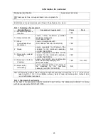
2.
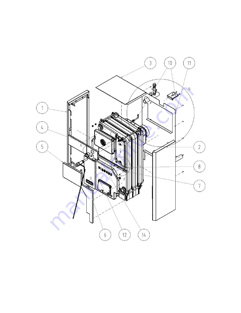
To fit sheet components with due connecting material according to Fig. no. 6.
Connecting spindle
10 pcs
Spring clip
10 pcs
Screw ST 4, 2x9, 5
10 pcs
Pivot
6 pcs
Nut M10
2 pcs
Nut M5
1 pc
Washer 5, 3
3 pcs
Washer 8, 4
1 pc
Screw M5x12
7 pcs
Screw M8x12
1 pc
Washer 10,5
2 pcs
Magnetic element
1 pc
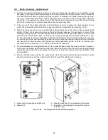
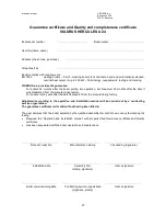
3.
According to the Fig. no. 7 – to cover the boiler.
1
Left side cover part with insulation
(3 pcs of connecting spindles, 2 pcs of pivots)
2
Right side cover part with insulation
(3 pcs of connecting spindles, 2 pcs of pivots)
3
Upper cover part (4 pcs spring clips)
4
Left front upper cover part
5
Left front cover part (3 pcs spring clips)
6
Right front lower part (3 pcs spring clips)
7
Brace (4 pcs connecting spindles)
8
The brace console
9
Console of the cleaning covering
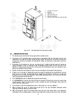
10 Pull rod of the smoke socket (complete)
11 Rear cover part
12 Right front cover part (2pcs pivots)
13 Magnetic element
14 Right front upper cover part
Summary of Contents for Hercules U 24
Page 30: ...30 ...
Page 32: ...32 Updating date 6 2013 GB ...


