Vezco VZ-IP-INTPRO Quick Start Manual Download Page 25


Video Intercom Door Station

·

Quick Start Guide 


18


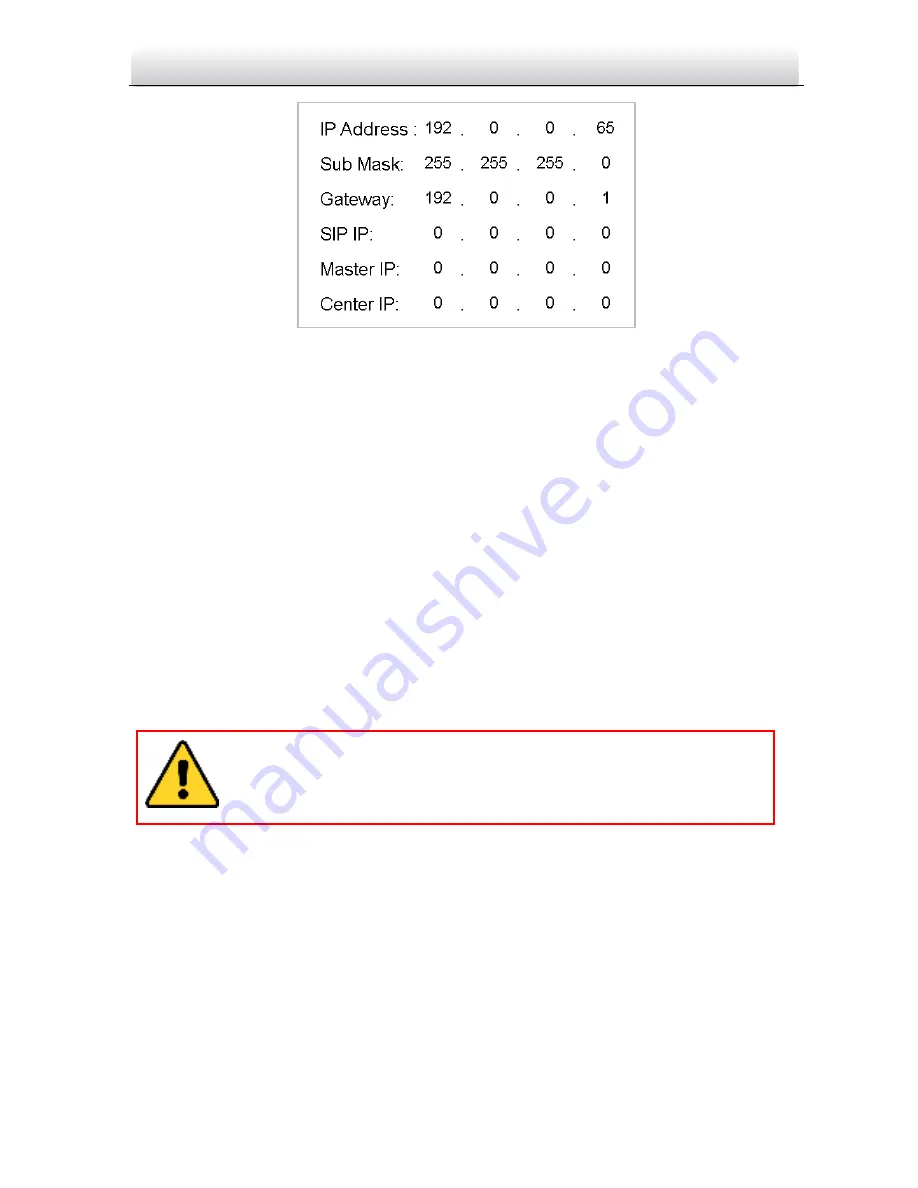
Figure 5-5 Network Parameters Settings Interface 
 

3.


Edit network parameters. 

1)


Move the cursor to parameters to be configured. 

2)


Press the 

key and the 

key to enter and exit the editing  mode. 

4.


Press the 

key to exit the network configuration interface after accomplishing 

network parameters settings. 


5.4


Changing Password 

Purpose: 

2 kinds of password are available when using the door station: configuration password 
(admin password) and card activation password. 

Configuration Password: 

It is necessary when you want to configure parameters of the 

door station, such as IP parameters, door station No., system type, and so on. 

Card Activation Password: 

It is necessary when you want to issue cards via password. 


Steps: 

1.


Go to the configuration mode. 

1)


Hold down the 

key and the 

key for 2s to enter the admin password interface. 

2)


Enter the admin password, and press the 

key. 

The default configuration password is 888999. We recommend you 
reset your password regularly, especially in the high security system, 
resetting the password monthly or weekly can better protect your 
product. 

Summary of Contents for VZ-IP-INTPRO

Page 1: ...Video Intercom Door Station Quick Start Guide...

Page 2: ...ER ATTACK VIRUS INSPECTION OR OTHER INTERNET SECURITY RISKS HOWEVER OUR COMPANY WILL PROVIDE TIMELY TECHNICAL SUPPORT IF REQUIRED SURVEILLANCE LAWS VARY BY JURISDICTION PLEASE CHECK ALL RELEVANT LAWS...

Page 3: ...the interference by one or more of the following measures Reorient or relocate the receiving antenna Increase the separation between the equipment and receiver Connect the equipment into an outlet on...

Page 4: ...t documentation for specific battery information The battery is marked with this symbol which may include lettering to indicate cadmium Cd lead Pb or mercury Hg For proper recycling return the battery...

Page 5: ...al region Please use the power adapter which is provided by normal company The power consumption cannot be less than the required value Do not connect several devices to one power adapter as adapter o...

Page 6: ...a bright places A blooming or smear may occur otherwise which is not a malfunction however and affecting the endurance of sensor at the same time Please use the provided glove when open up the device...

Page 7: ...Alarm Device Output Wiring 10 3 Installation 11 3 1 Installation of Door Station 11 3 1 1 Gang Box 11 3 1 2 Wall Mounting with Gang Box 12 4 Before You Start 14 5 Local Operation 15 5 1 Keys Descript...

Page 8: ...oor Station Quick Start Guide 1 1 Appearance 1 1 Appearance of Door Station Figure 1 1 Front View Figure 1 2 Rear View Table 1 1 Descriptions Keys No Description 1 Low Illumination Supplement Light 2...

Page 9: ...Video Intercom Door Station Quick Start Guide 2 No Description 3 Loudspeaker 4 LCD Display Screen 5 Card Induction Area 6 Keypad 7 Call Button 8 Call Center Key 9 Microphone 10 TAMPER...

Page 10: ...Video Intercom Door Station Quick Start Guide 3 2 Terminal and Wiring 2 1 Terminal Description Figure 2 1 Terminals and Interfaces...

Page 11: ...C 12V DC 12V Power Supply Input READER A1 12V Power Supply Output A2 GND Grounding A3 W1 Data Input Interface Wiegand Card Reader Data1 A4 W0 Data Input Interface Wiegand Card Reader Data0 A5 BZ Card...

Page 12: ...al Port Debugging Power Supply DOOR C1 12V Power Supply Output C2 GND Grounding C3 NC2 Door Lock Relay Output NC C4 COM2 Grounding Signal C5 NO2 Door Lock Relay Output NO C6 NC1 Door Lock Relay Output...

Page 13: ...iring Terminal NC1 COM1 is set as default for accessing magnetic lock electric bolt terminal NO1 COM1 is set as default for accessing electric strike Toconnect electric lock in terminal NO2 COM2 NC2 i...

Page 14: ...ring Door Magnetic Wiring Figure 2 3 Door Magnetic Wiring To connect the door magnetic it is required to set the output of terminal AI2 to be door magnetic with Batch Configuration Tool or VEZPRO 2 2...

Page 15: ...hen the card reader is power on please reboot the card reader after configuring the DIPswitch The DIP switch description is shown in the following table No Description How to Configure 1 4 Set the RS...

Page 16: ...2 5 External Elevator Controller Wiring You can connect the door station to the elevator controller via RS 485 interface There are 4 groups of RS 485 interfaces on the elevator controller group A grou...

Page 17: ...r Station Quick Start Guide 10 2 2 6 Alarm Device Input Wiring Alarm Device Input Wiring Figure 2 7 Alarm Device Input Wiring Alarm Device Output Wiring Alarm Device Output Wiring Figure 2 8 Alarm Dev...

Page 18: ...sure your power supply matches your door station Make sure all the related equipment is power off during the installation Check the product specification for the installation environment 3 1 Installa...

Page 19: ...e hole should be larger than that of the gang box The suggested size of hole is 343 5 length 113 5 width 55 5 depth mm 2 Insert the gang box into the hole and fix it with 4 PA4screws Screw Screw Figur...

Page 20: ...ercom Door Station Quick Start Guide 13 5 Put the door station into the gang box Figure 3 3 Install the Door Station 6 Fix the door station to the gang box with 4 crews Figure 3 4 Tighten the Screws o...

Page 21: ...RO refer to 6 1 Activating Device Remotely To activate the device locally refer to 5 2 Activating Device To configure the key parameters of device on the user interface of door station you are require...

Page 22: ...Descriptions 1 Key Description Numeric Key 2 Numeric Key 4 Numeric Key 6 Numeric Key 8 Call Key When calling residents or center Confirm Return Delete 5 2 Activating Device You cannot use the door sta...

Page 23: ...4 Press the key to complete the activation Key Description Key Description 1 1 6 6mnoMNO 2 2abcABC 7 7pqrsPQRS 3 3defDEF 8 8tuvTUV 4 4ghiGHI 9 9wxyzWXYZ 5 5jklJKL 0 0 STRONG PASSWORD RECOMMENDED We hi...

Page 24: ...e key for 2s to enter the admin password interface 2 Enter the admin password and press the key Figure 5 3 Admin Password Interface The default admin password is 888999 2 Enter the network parameters...

Page 25: ...sword admin password and card activation password Configuration Password It is necessary when you want to configure parameters of the door station such as IP parameters door station No system type and...

Page 26: ...admin password is 888999 2 Press the numeric keys 4 and 6 to switch to the password settings interface Figure 5 7 Password Settings Interface Changing Configuration Password Steps 1 On the password s...

Page 27: ...ation Password Changing Interface 2 Enter the old password and the new password and confirm the new one 1 Move the cursor to parameters to be configured 2 Press the key to enter or exit the editing mo...

Page 28: ...y inputting the password is only available in the network intercom system Steps 1 Enter the key and the Room No 2 Enter the password and the key The password varies according to different rooms The de...

Page 29: ...ice Activation via Batch Configuration Tool and Activation via VEZPRO are supported Here take activation via Batch Configuration Tool as example to introduce the device activation Please refer to the...

Page 30: ...via batch configuration tool as example Steps 1 Select an online activated device and click the Edit NET Parameters button Figure 6 3 Clicking Edit NET Parameters Button 2 Change the device IP addres...

Page 31: ...to configure the device remotely 3 ways for adding the device are supported adding active online devices within your subnet adding device by IP address and adding device by IP segment Here take addin...

Page 32: ...t for configuration If you add devices in batch please make sure selected devices have the same user name and password 6 3 2 Adding by IP Address Purpose You can add the device by entering IP address...

Page 33: ...ng by IP Address 4 Click the OK button to add the device to the device list You cannot add the device s to the device list if the user name and password are not identical When you add devices by IP Ad...

Page 34: ...e between two devices is recommended to be longer than 10 meters Here devices refer to indoor station outdoor station and master station Wiring Cables Cable Specification Power Cord of Door Station RV...

Page 35: ......

Reviews: