Rev. 5/8/2019
ZLTT MANUAL
Copyright 2019 Vestil Manufacturing Co.
Page 12 of 15
b. Replace the valve if the poppet does not move.
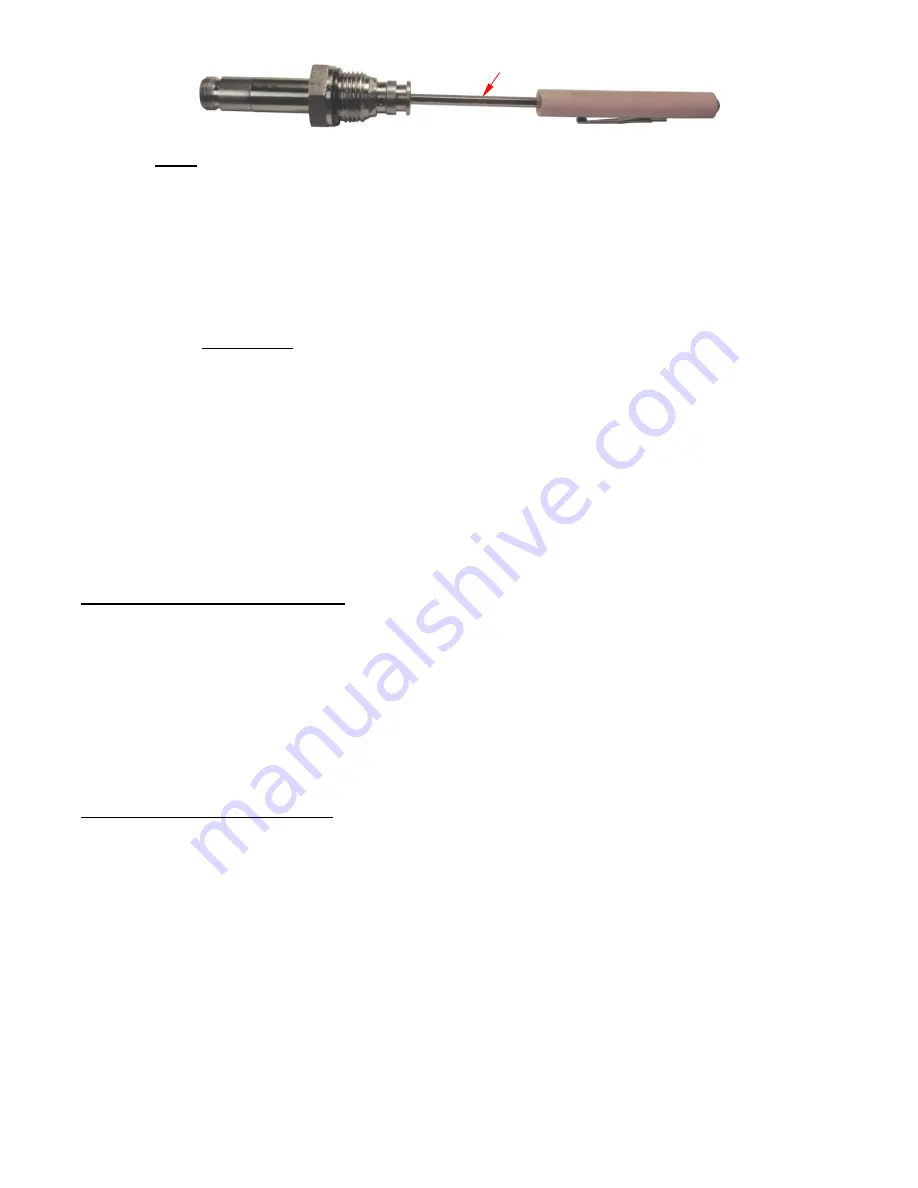
NOTE: A flow control spool is located inside the lowering valve cavity of the manifold. It is visible once
the valve is removed. The outer body is threaded into the cavity. The inner part of the spool
has a spring behind it and can move under gentle pressure. Press gently on the center of the
spool with a small, standard head screwdriver to determine if it can move freely up and down.
If the spool does not move, the spring or the entire spool must be replaced. Contact
Technical
Service
to discuss your observations if you are uncertain whether the spring or spool must be
replaced.
c. Reinstall the screen, the O-ring, and the outer seal.
8.
Reinstall the valve in the manifold and tighten it with 20 lb∙ft of torque.
B. Bleeding air from the hydraulic system
.
If the tabletop moves slowly while either the LOWER, or TILT DOWN, button is pressed, then air might be
present in the cylinders. Air can cause one or both of the velocity fuses to close. A closed fuse prevents oil from
flowing out of its cylinder. Air must be bled from the system to correct the problem.
•
Lower the tabletop completely and unload it.
•
If the tabletop moves slowly when the LOWER button is pressed, then unpin the higher end of the lifting
cylinders and lay them on the base frame. If the tabletop moves slowly when the TILT DOWN button is
pressed, then unpin the
•
Hold a rag over the hose fitting at the blind end of the cylinder.
•
Loosen the hose fitting by ½ turn.
•
Push the cylinder rod in. Air will sputter from the fitting.
•
Tighten the hose fitting when no more air escapes is present—only a clear stream of oil flows from it.
•
Check the oil level in the reservoir. If the surface of the oil is more than 1 to 1½ in. below the fill hole, add oil.
Bring the surface level up to within 1” and 1½” of the fill hole.
Record of Original Condition
Make a record of the unit in its original condition before putting it into service. Thoroughly photograph the unit
from all sides. Include close range photos of each label applied to the unit, all 4 anchor bolts, and all pivot points.
Use the handheld controller to elevate the table. Photograph the elevated table. Describe the motion of the table
as it rises as well as how it sounds. Tilt the table. Take more photographs and again describe the motion and
sounds heard as the power unit operates. Un-tilt the tabletop and lower it to the home position. Describe the
motion and sound of the table as it lowers. Collate all documentation and photographs. This record establishes
“original condition”. Compare the results of every inspection to this record. Repair or replace all parts that no
longer are in original condition. Purely cosmetic changes are not changes from original condition. However,
touchup paint should be applied to all areas where the surface coating is damaged as soon as the damage
occurs.
Inspections & Maintenance
Inspect the unit regularly for changes from
pages 4-7 to identify parts listed in these inspection procedures. Contact
not addressed in these procedures or if you are unsure that the table is safe to continue using.
A. Inspect the following parts
before each use
.
1. Side guards: Confirm that the side guards are properly and securely attached to the side walls.
2. Frame, legs, and tabletop: Look for damaged welds, warps, cracks, or other deformations. Give special
attention to the cylinder mounting brackets, i.e. the structures that connect the cylinders to the frame.
3. Hydraulic system: Check all hoses for kinks, pinches, cuts, punctures, etc. Examine hose fittings and
couplers. Make sure there are no oil leaks. Cycle the table from home position to the fully raised and tilted
position and then back to home. Listen to the motor for unusual sounds during operation and watch the legs
and tabletop. Confirm that the table moves smoothly, e.g. without binding or jerking. The tabletop should
rotate evenly and at a uniform rate. Make sure that the cylinders are straight and undamaged.
4. Limit switches: Confirm normal operation of all limit switches by cycling the tabletop.
a. Push the LIFT button. The motor should turn off when the tabletop reaches its fully raised position.
b. Press the TILT UP button. A limit switch should turn off the motor when the tabletop is tilted 45°.
c. Press the TILT DOWN button until the tabletop is no longer tilted. Then, press the LOWER button.
The motor should turn off when the tabletop is returned to the home position.
5. Fasteners: check bolts and nuts. Make sure all fasteners are tightly connected.
Screwdriver


