

Rev. 3.19.2020
LAD-TRN MANUAL
Copyright 2020 Vestil Manufacturing Co.
Page 9 of 12
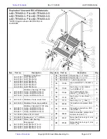
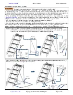
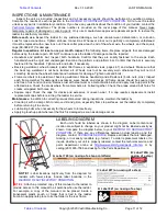
Step 3: Install the plugs, caps, and wheels.
a) Install the plastic plugs and square caps in the
leg tubes. First, press the 1in. plastic plug into
the leg tubes. Then, press the square caps over
the plugs and onto the ends of the legs. If
necessary, use a rubber mallet to gently tap the
plugs and caps into place.
b) Press a plug into each end of the cross brace.
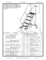
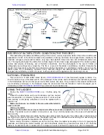
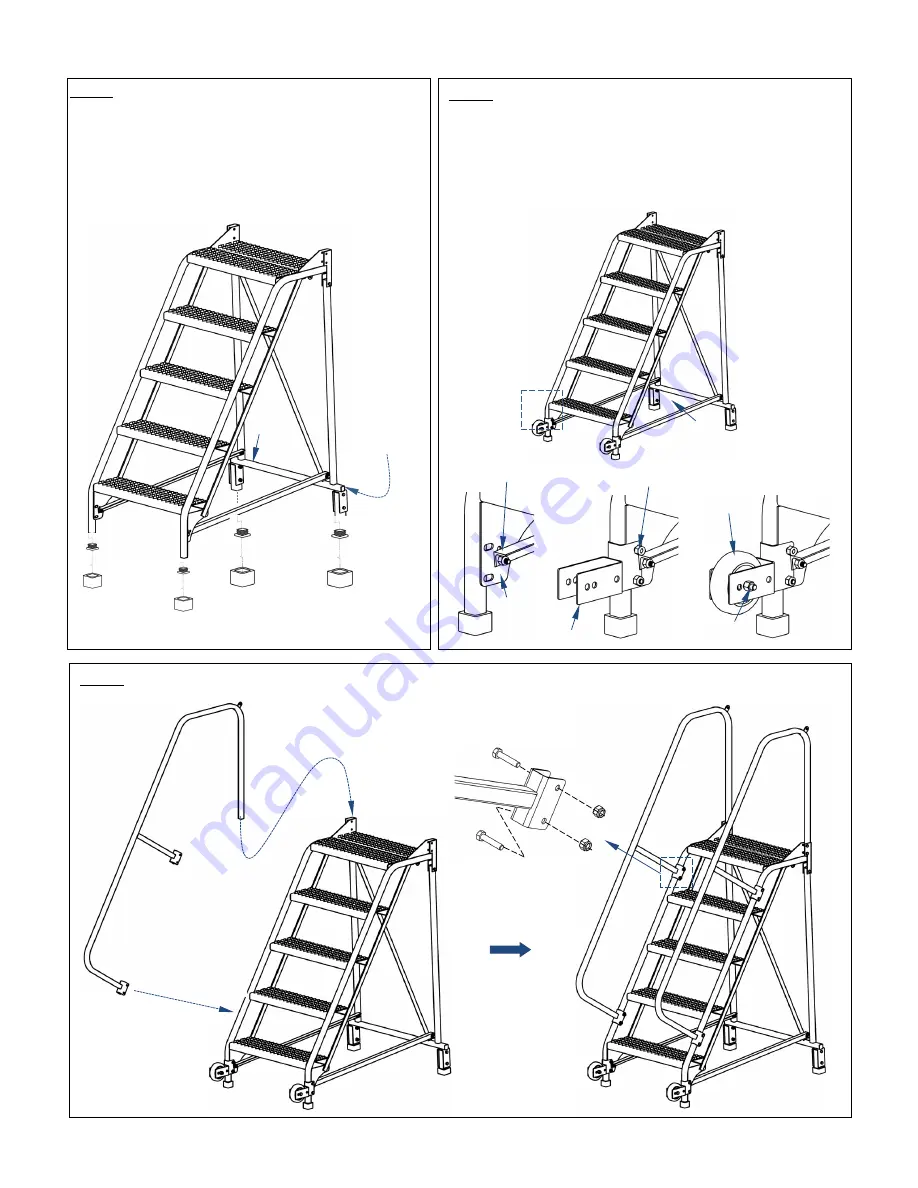
Step 5: Attach the handrails.
Ladder
assembly
1”x1”
square cap
99-024-027
Insert plug
99-025-025
Cross
brace
Handrail
11060
37021
1” black
plastic plug
99-025-025
1.5”x1.5”
square cap
99-024-028
1.5” black
plastic plug
21-024-016
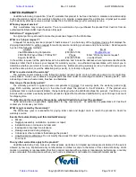
Step 4: Fasten the wheel brackets (44-514-313; “caster
tilter frames” in exploded views) to the ladder assembly
with
5
/
16
”-18 x 1
3
/
4
” bolts (11060) and lock nuts (37021).
The caster brackets fit
between
the base supports and
support brackets (see step 2 on p. 8). Attach the wheels
(16-132-009) to the wheel bracket using the hardware
indicated. Tighten connection A.
Connection A: left
loose in step 2
44-514-313
11060 & 37021
Support
bracket
Base support
16-132-009
11113 + 37024