


Copyright 2017 Vestil Manufacturing Corp.
Page 4 of 5
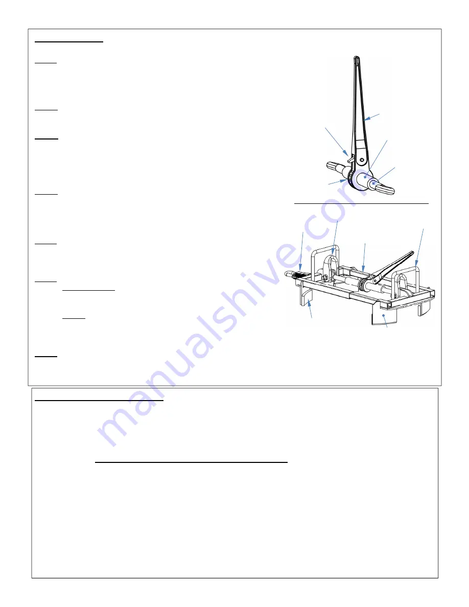
Using the lifter:
This product can be used either as a below-the-hook lifting device attached to a hoist, or as a forklift attachment.
Step 1: Make sure that the lifter is open wide enough to fit over the top
of your drum. Moving the handle back-and-forth either extends or
retracts the lifter. The orientation of the ratchet pawl determines
whether moving the handle causes extension or retraction. Push the
upper part of the pawl down to change direction.
Step 2: Set the lifter on top of your drum. The drum brackets should
slide around the side of the drum so that the telescoping arms rest on
top of the drum.
Step 3: Set the pawl appropriately to retraction the lifter. Move the
handle back-and-forth to bring the two sides of the lifter towards each
other. Move the handle until the lifter is securely clamped to the top of
the drum. Inspect the clamp and make sure that all 4 rim supports are
below the drum rim and are firmly pressed against the side of the
drum.
Step 4: Connect the lifter to a hoist or mount it on a fork of your lift
truck.
a. Hoist: attach a chain sling to both shackles and to the hoist hook.
b. Forklift: drive a fork through both fork loops. Attach the safety
strap to the carriage of your forklift
without slack
.
Step 5: Test the clamp by raising the drum just a few inches above the
ground. Watch the drum and lifter for approximately 10 seconds to be
certain that the lifter has an adequate clamp on the rim. If the clamp is
adequate, proceed to the next step.
Step 5: Transport the drum to the desired location.
a. Overhead hoist: Lift the drum ~ 5-6 inches above the ground.
Stand to the side of the drum and stabilize it by grasping the
lifter. Minimize drum swing by moving the hoist
slowly
.
b. Forklift: drive slowly, particularly while turning. Reduce speed
during all turns. Apply the brakes gradually. The lifter should
not slide towards the tip of the fork if the safety strap is
attached properly.
Step 6: Before lowering the drum, make sure that it is not swinging, spinning, etc. Slowly lower the drum until it is
stably supported by the ground. Disconnect the lifter from the hoist or demount the lifter from the forklift. Reverse
direction of the load binder by pressing down the upper part of the pawl. Move the handle back-and-forth to release
the clamp.
Inspections & Maintenance:
Before using the lifter for the first time, make a written record of its appearance. Include observations about
shackle hardware, drum brackets and rim supports, the load binder, and the telescoping arms (see diagrams in “Using
the lifter”). Also include observations about the fork loops and safety strap (and hook). Extend and retract the lifter by
selecting the appropriate pawl configuration and moving the handle back-and-forth. Describe how the spindles wind
into their receivers. How much force is required to work the ratchet mechanism? This record establishes “normal
condition”. During future inspections, compare your observations to the written record to determine if the unit is in
normal condition.
DO NOT use the lifter unless it is in normal condition
.
Visually examine the following elements
before each use
.
Shackles and hardware: Check for cracks,
deformations, and severe wear.
1. Load binder: Confirm that both spindles wind into, and out of, their receivers smoothly. The pawl should firmly
engage the teeth of the ratchet gear in both directions. Spindle and receivers should be straight, undamaged,
and free of significant rust/corrosion.
2. Frame (Telescoping arms, drum brackets, rim supports, fork loops, etc.): Check welds and frame members for
breaks and severe rusting/corrosion. Remove rust/corrosion with a brush or steel wool. Clean the area and apply
touchup paint. Frame members should be square and rigid. Arms should telescope smoothly (without binding).
Lubricate arms with a silicone wax whenever necessary.
3. Safety strap and hook: examine the strap for cuts, tears, etc. Verify that the hook latch works properly.
4. Make a dated record of the repairs, adjustments and/or replacements. Only install manufacturer-approved
replacement parts. Deformities, cracks, and severe wear of either arm warrants immediate replacement of the
entire unit
.
Rim support (goes
underneath the
drum rim)
Ratchet pawl
(press down
to change
direction
Handle
Spindle
Safety
strap
Telescoping
arm
Fork
loop
Drum bracket
Ratchet
mechanism
Receiver
Shackle