VESTEL OPSATOM Manual Download Page 7

DS PROJECTS

7

© APPLICATION ENGINEERING
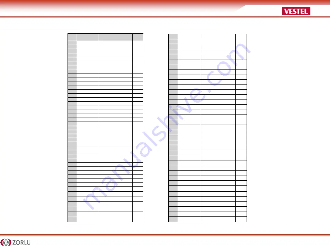
PIN CONNECTIONS (JAE TX25-80)


PIN 

NO


Signal


Description


I/O


1


NC 

DisplayPort 

OUT 

2


NC 

DisplayPort 

OUT 

3


GND 

Ground 

4


NC 

DisplayPort 

OUT 

5


NC 

DisplayPort 

OUT 

6


GND 

Ground 

7


NC 

DisplayPort 

OUT 

8


NC 

DisplayPort 

OUT 

9


GND 

Ground 

10


NC 

DisplayPort 

OUT 

11


NC 

DisplayPort 

OUT 

12


GND 

Ground 

13


NC 

DisplayPort 

OUT 

14


NC 

DisplayPort 

OUT 

15


NC 

DisplayPort 

IN 

16


GND 

Ground 

17


TMDS_CLK- 

DVI-D 

OUT 

18


DVI-D 

OUT 

19


GND 

Ground 

20


TMDS0- 

DVI-D 

OUT 

21


TMDS0+ 

DVI-D 

OUT 

22


GND 

Ground 

23


TMDS1- 

DVI-D 

OUT 

24


TMDS1+ 

DVI-D 

OUT 

25


GND 

Ground 

26


TMDS2- 

DVI-D 

OUT 

27


TMDS2+ 

DVI-D 

OUT 

28


GND 

Ground 

29


DVI_DDC_DATA 

DVI_D 

I/O 

30


DVI_DDC_CLK 

DVI_D 

I/O 

31


DVI_HPD 

DVI_D 

IN 

32


GND 

Ground 

33


+12V~+19V 

Power 

34


+12V~+19V 

Power 

35


+12V~+19V 

Power 

36


+12V~+19V 

Power 

37


+12V~+19V 

Power 

38


+12V~+19V 

Power 

39


+12V~+19V 

Power 

40


+12V~+19V 

Power 

41


PWROK 

System power OK 

OUT 

42


WAKE 

System wake 

OUT 

43


RSVD 

Reserved pins 

44


RSVD 

Reserved pins 

45


RSVD 

Reserved pins 

46


RSVD 

Reserved pins 

47


RSVD 

Reserved pins 

48


RSVD 

Reserved pins 

49


RSVD 

Reserved pins 

50


SYS_FAN 

System Fan Control 

OUT 

51


UART_RXD 

UART 3.3V 

IN 

52


UART_TXD 

UART 3.3V 

OUT 

53


GND 

Ground 

54


StdA_SSRX- 

USB3.0 

IN 

55


St 

USB3.0 

IN 

56


GND 

Ground 

57


StdA_SSTX- 

USB3.0 

OUT 

58


St 

USB3.0 

OUT 

59


GND 

Ground 

60


USB_PN2 

USB 

I/O 

61


USB_PP2 

USB 

I/O 

62


GND 

Ground 

63


USB_PN1 

USB 

I/O 

64


USB_PP1 

USB 

I/O 

65


GND 

Ground 

66


USB_PN0 

USB 

I/O 

67


USB_PP0 

USB 

I/O 

68


GND 

Ground 

69


AZ_LINEOUT_L 

Audio-Lch 

OUT 

70


AZ_LINEOUT_R 

Audio-Rch 

OUT 

71


CEC 

Consumer Electronic Control 

I/O 

72


PB_DET 

Pluggable Board Detect 

OUT 

73


PS_ON 

Pluggable Signal ON 

IN 

74


PWR_STATUS 

PowerGood 

OUT 
(OC) 

75


GND 

Ground 

76


GND 

Ground 

77


GND 

Ground 

78


GND 

Ground 

79


GND 

Ground 

80


GND 

Ground 


Summary of Contents for OPSATOM

Page 1: ...DS PROJECTS 1 APPLICATION ENGINEERING OPS Presentation Vestel Application Engineering Department 2017 ...

Page 2: ...age SSD 256 GB HDD 500 GB SSD 256 GB HDD 500 GB SSD 256 GB HDD 500 GB Internal Storage 8 GB Nand Flash SD Card Up to 32 GB SSD 256 GB HDD 500 GB SSD 256 GB HDD 500 GB Internal Storage 4 GB HDD 500 GB I O Ports 1 x RJ45 2 x USB2 0 1 x Display Port 1 x Headphone 3 5 mm jack 1 x Microphone 3 5 mm jack 2 x WiFi antenna connector 1 x Power button 1 x Reset button 1 x RS232 3 x USB3 0 1 x USB2 0 1 x HDM...

Page 3: ...PSSL650 1 HDMI 5 RJ45 10 100 1000 Mbps Ethernet 2 Microphone Headphone 3 5mm jack 6 RS232 3 3 x USB 3 0 ports 7 On Off Button 4 USB 2 0 port 8 2 x WiFi Antenna Connectors Input Output Connections The connections are illustrated as shown below TOP VIEW BOTTOM VIEW ...

Page 4: ...ut Output Connections The connections are illustrated as shown below TOP VIEW BOTTOM VIEW 1 RJ45 10 100 1000 Mbps Ethernet 5 Reset Button 2 2 x USB 2 0 ports 6 Microphone 3 5mm jack 3 Display Port 7 Headphone 3 5mm jack 4 On Off Button 8 2 x WiFi Antenna Connectors ...

Page 5: ...SRK150 Input Output Connections The connections are illustrated as shown below TOP VIEW BOTTOM VIEW 1 WIFI Antenna Connector 5 RJ45 10 100 Mbps Ethernet 2 SD Card Slot 6 2 x USB 2 0 Ports 3 Microphone Port 3 5mm jack 7 USB OTG 4 Headphone Port 3 5mm jack ...

Page 6: ... 80 pin OPS standard connection interface Interconnectionof the product and another board i e docking board monitor board or main board is provided by JAE TX 24TX25 plug and receptacle connectors Left Plug connector p n TX25 80P Right Receptacle connector p n TX24 80P Plug Connector TX25 Pinout Receptacle Connector TX24 Pinout Connector series image reference only ...

Page 7: ...6 12V 19V Power 37 12V 19V Power 38 12V 19V Power 39 12V 19V Power 40 12V 19V Power 41 PWROK System power OK OUT 42 WAKE System wake OUT 43 RSVD Reserved pins 44 RSVD Reserved pins 45 RSVD Reserved pins 46 RSVD Reserved pins 47 RSVD Reserved pins 48 RSVD Reserved pins 49 RSVD Reserved pins 50 SYS_FAN System Fan Control OUT 51 UART_RXD UART 3 3V IN 52 UART_TXD UART 3 3V OUT 53 GND Ground 54 StdA_SS...

Page 8: ... it in a warm environment A sudden temperature change of 10 C may cause some of the internal parts to malfunction Do not put your product on an uneven surface Points to be taken into consideration while clean ing the product Your system must be turned off while cleaning the product Please use a soft and damp piece of cloth for cleaning its surface Do not use chemical cleansers to clean the product...

Page 9: ...DS PROJECTS 9 APPLICATION ENGINEERING Replacing HDD RAM WIFI OPSSL630 OPSSL650 Models PL806 SSD COVER Don t use these sockets RAM1 RAM 2 ...

Page 10: ...DS PROJECTS 10 APPLICATION ENGINEERING Replacing HDD or SSD OPSSL630 OPSSL650 OPSJ1900 Models PL806 SSD or HDD replace from SSD CVR with 4 screws Holder position should be bottom side ...

Page 11: ...DS PROJECTS 11 APPLICATION ENGINEERING Replacing WIFI RAM OPSJ1900 Models PL806 Remove 3 screws WIFI RAM 1 RAM 2 ...

Page 12: ...DS PROJECTS 12 APPLICATION ENGINEERING Docking Board ...

Page 13: ...DS PROJECTS 13 APPLICATION ENGINEERING Docking Board Verification Test after Swapping any component ...

Page 14: ...DS PROJECTS 14 APPLICATION ENGINEERING Power Status ...

Page 15: ...return it to its default state Windows 10 has your answer The operating system provides a number of options that let you restore your computer to an earlier state Here s how to reset your PC in Windows 10 Navigate to Settings You can get there by clicking the gear icon on the Start menu 1 Navigate to Settings You can get there by clicking the gear icon on the Start menu ...

Page 16: ...DS PROJECTS 16 APPLICATION ENGINEERING How to Reset Your Windows 10 PC 2 Select Update security 3 Click Recovery in the left pane ...

Page 17: ... this PC Go back to an earlier build and Advanced startup Reset this PC is the best option for starting fresh Advanced startup lets you boot off a recovery USB drive or disc and Go to an earlier build is made for Windows Insiders who want to roll back to a previous version of the OS 4 Click Get started under Reset this PC ...

Page 18: ...ults and apps will be uninstalled 6 Select Just remove my files or Remove files and clean the drive if you chose to remove everything in the prior step Cleaning the drive takes a lot longer but will make sure that if you are giving the computer away the next person will have a hard time recovering your erased files If you are keeping the computer choose Just remove my files How to Reset Your Windo...

Page 19: ...Next if Windows warns you that you won t be able to roll back to a prior version of the OS How to Reset Your Windows 10 PC 8 Click Reset when prompted Windows will then restart and take several minutes to reset itself 9 Click Continue when prompted ...

Page 20: ...ld be chosen under Device option File system should be chosen as NTFS windows image iso should be chosen as ISO Image Picture 2 1 Click on start button to start the process Picture 3 2 You will see Done after the process is finished Picture 4 3 Power off the device with operating system problem 4 Plug USB Drive and power on 5 After power on press F7 and select USB drive with UEFI option as shown P...

Page 21: ...DS PROJECTS 21 APPLICATION ENGINEERING WINDOWS 10 REINSTALLATION VIA USB FLASH DRIVE Picture 1 Picture 2 Picture 3 Picture 4 Picture 5 ...

Page 22: ...NEERING OPS INTEL Bios Update Procedure Requirements USB Flash Drive which has minimum 32MB Bios Update files are specific for product that will share via Customer Support Step 1 Copy bios update files in to the Bootable Flash memory ...

Page 23: ...date Procedure Step 2 Plug the Bootable Flash Memory to OPS USB Input Port Step 3 Plug keyboard to OPS USB Input Port Step 4 Press power on button and run IWB Step 5 While Bios Logo shown on the screen press F7 for Boot Menu Step 6 Select Bootable USB memory ...

Page 24: ...ENGINEERING OPS INTEL Bios Update Procedure Step 7 Run the update batch file f bat in DOS commad prompt Step 8 Bios Update Completed Succesfuly screen shown below Step 9 Please Unplug Plug AC 220V power cable after update proses ...

Page 25: ...DS PROJECTS 25 APPLICATION ENGINEERING OPS ARM SW Update Rockchip Driver Installation 1 Download the ARM OPS tool rar file from the link shared with you 2 Extract it to your local drive ...

Page 26: ...DS PROJECTS 26 APPLICATION ENGINEERING OPS ARM SW Update 3 Open Release_DriverAssistant folder Then double click DriverInstall exe Wait till the installation ends ...

Page 27: ...DS PROJECTS 27 APPLICATION ENGINEERING OPS ARM SW Update 4 Copy android folder to this address C Users Your_User_Name No need to do these steps again once it has done for the first time usage ...

Page 28: ...DS PROJECTS 28 APPLICATION ENGINEERING OPS ARM SW Update Adnroid Image Installation 1 Run AndroidTool exe from AndroidTool_Release_v2 1 AndroidTool_ Release folder ...

Page 29: ...DS PROJECTS 29 APPLICATION ENGINEERING OPS ARM SW Update 2 Connect ARM OPS to your computer via USB OTG cable 3 Turn on the OPS by pressing the Power On Off button at least 1 4 sec from docking board ...

Page 30: ...After the Android boot logo is appeared on the screen then there will write Found one MSC Device NOTE If label at bottom bar could not turn to Found one MSC Device follow these steps Connect a mouse to the ARM OPS Go to Settings menu Then select STORAGE From here at the right corner of the screen click USB computer connection icon ...

Page 31: ...DS PROJECTS 31 APPLICATION ENGINEERING OPS ARM SW Update Select Mass Storage After these steps there must be written Found one MSC Device on the tool ...

Page 32: ...ION ENGINEERING OPS ARM SW Update W ALTERNATIVE WAY If OPS is not connecting as Mass Storage Device please follow these steps Unscrew OPS top bracket in order to reach OPS Main Board Short the J34 with any material Cable etc ...

Page 33: ...ING OPS ARM SW Update W ALTERNATIVE WAY If everything is OK There will write MASKROM in red rectangle area Then Load Image File by clicking the button marked with 1 A pop up menu will appear and select Android update image file from here ...

Page 34: ...Upgrade Firmware tab then click Firmware button from the tool after then select update img which is given 6 Click Switch button This will put ARM OPS into image update mode 7 Click Upgrade button to start the image update Then wait till the system opens automatically ...

Page 35: ...his problem correctly Try to find out what it is Determine what causes the problem and under which category it falls Write down the error codes and messages displayed on the screen if possible Contact technical support to get support Frequently Asked Questions Sound Issues Problem Sound system is not working Check the following Be sure that sound volume is not low and sound is not muted Ensure tha...

Page 36: ...te down the error codes and messages displayed on the screen if possible Contact technical support to get support Frequently Asked Questions Sound Issues Problem Sound system is not working Check the following Be sure that sound volume is not low and sound is not muted Ensure that the sound driver and its application are installed properly Check cable connections Problem External microphone and au...

Page 37: ...ed the power supply to see if it turned things on but what if it s not turning everything on Or if the voltages are wrong This POST test helps us narrow the cause down to the power supply A replacement would usually be necessary Long continuous beep tone Memory failure This is usually what you hear when one or both of your Random Access Memory RAM sticks goes bad If there is more than one stick in...

Page 38: ...DS PROJECTS 38 APPLICATION ENGINEERING THANK YOU Vestel Application Engineering Department HBB 2017 ...

Reviews: