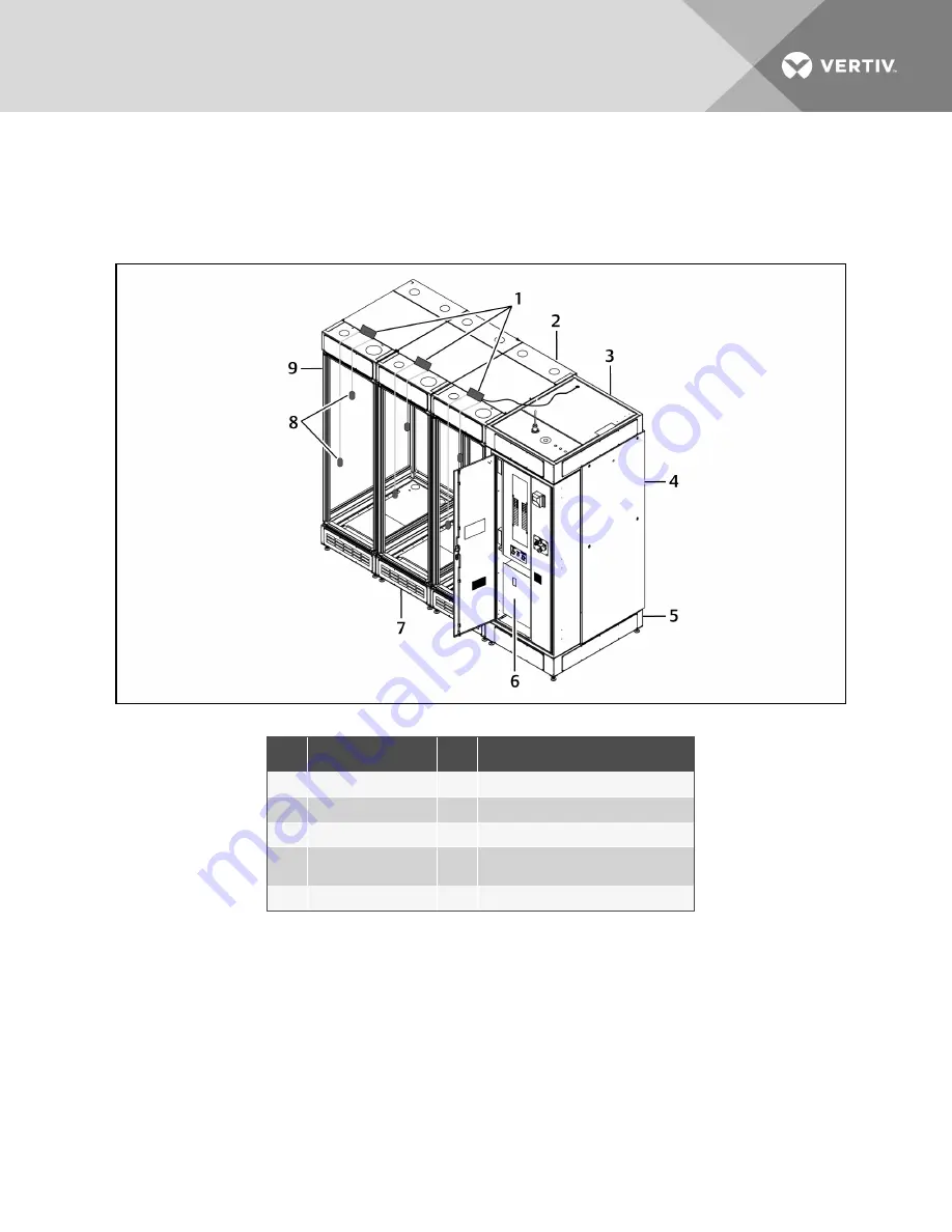
2. Locate the coiled CAN cable on top of the PDX/PCW.
3. Uncoil the cable, route it to 2T sensor on the adjacent rack and connect it to the 2T sensor.
4. Connect all adjacent 2T sensors with supplied CAN cable.
Figure 4.24 2T sensor and probe placement
NO.
DESCRIPTION
NO.
DESCRIPTION
1
2T sensors
6
Control panel and Fire-suppression system
2
Top plenum-rack
7
Base plenum-rack
3
Top plenum-PDX/PCW
8
2T-sensor probes
4
PDX/PCW cooling unit
9
DCR rack (standard doors; panels
and partitions removed for clarity)
5
Base plenum-PDX/PCW
4.10.6 Locate and Install 4-pin HVAC Fault/Emergency Fan Control,
Thermal-unit Shutdown Connector Cable (P2)
The wires may be identified by their color:
•
Orange wires are HVAC fault/Run Emergency Fans
•
Yellow wires are thermal-unit shutdown.
1. Locate this cable (with the 4-pin connector) in the bottom of the DCR control panel.
2. Referring to Figure 4.25 on the next page, route the cable out of the grommet in the top,
right-hand corner of the Control Panel and Fire Suppression module.
Vertiv
| SmartRow DCR Installer/User Guide |
41
Summary of Contents for SmartRow DCR
Page 6: ...Vertiv SmartRow DCR Installer User Guide 6...
Page 12: ...Vertiv SmartRow DCR Installer User Guide 12 This page intentionally left blank...
Page 52: ...Vertiv SmartRow DCR Installer User Guide 52 This page intentionally left blank...
Page 66: ...Vertiv SmartRow DCR Installer User Guide 66 This page intentionally left blank...
Page 70: ...Vertiv SmartRow DCR Installer User Guide 70 This page intentionally left blank...
Page 72: ...Vertiv SmartRow DCR Installer User Guide 72 This page intentionally left blank...
Page 76: ...Vertiv SmartRow DCR Installer User Guide 76 This page intentionally left blank...
Page 82: ...Vertiv SmartRow DCR Installer User Guide 82 This page intentionally left blank...
Page 101: ......


