3
2.4.4 Connecting Battery Cable
The power system can be accessed in one group of batteries controlled by a battery MCB.
The battery MCB is located on the front panel of the power system and the battery
connection terminal is at the rear right side of the subrack. During connection, connect the
negative battery cable to the battery terminal '-' and then connect the positive battery
cable to the battery terminal '+'. Terminal connection method:
As shown in Figure 2-10,
use a flat-blade screwdriver, gently pull out the insulation film to prevent short circuit,
loosen the screw, insert the corresponding cable end into the corresponding positive and
negative terminals, and then tighten both screws. After that cover the terminal screw with
the insulation film to avoid accidental short circuit.
Screwdriver
Battery input
Screwdriver
Battery input
Battery input terminal
Figure 2-10 Illutration of battery connection terminal
2.4.5 Connecting Communication Cable
Connecting M225S dry contact output port
The controller is configured with two pairs of alarm dry contact output (DO1 ~ DO2) as
standard configuration and four expanded outputs (DO3 ~ DO6) as optional. The dry
contact that generating corresponding alarm is normally closed, users can connect
according to actual needs. When wiring, connect the multi-core communication cable with
the pipe terminal to the corresponding dry contact according to the dry contact silkprint
on the controller, and then insert the terminal into the controller front panel. The position
of communication terminal and port definition are shown in Figure 2-11 (Users need to
prepare signal cable themselves).
Figure 2-11 Illutration of controller front panel
Connecting RS232 port of M225S controller
The RS232 port is used for communication with the host. The correlation of the RS232 and
DB9 port on the host is shown in Table 2-2. When wiring, connect the multi-core
communication cable with the pipe terminal to the corresponding terminal according to
the RS232 port silkprint on the controller, and then insert the terminal into the controller
front panel, as shown in Figure 2-11 (Users need to prepare signal cable themselves).
Table 2-2 Correlation of ports
RS232 port
DB9 port
1 (Tx)
2
2 (Rx)
3
3 (GND)
5
Connecting M831A dry contact output port
The controller is configured with four pairs of alarm dry contact output (DO1 ~ DO4) as
standard configuration and two routes of DI input and one route of RS485 output. The dry
contact that generating corresponding alarm is normally closed, users can connect
according to actual needs. The two routes of DI input only need to input DI dry contact and
no need to input external power. When wiring, connect the multi-core communication
cable with the pipe terminal to the corresponding dry contact according to the dry contact
silkprint on the controller, and then insert the terminal into the controller front panel. The
position of communication terminal and port definition are shown in Figure 2-12 (Users
need to prepare signal cable themselves).
DO1-COM
1 2 3 4 5 6 7
8 9 10 11 12 13 14
DO1-NC/NO
DO2-COM
DO2-NC/NO
DO3-COM
DO3-NC/NO
DO4-COM
DO4-NC/NO
DI1-1
DI1-2
DI2-1
DI2-2
RS485A
RS485B
Figure 2-12 Illutration of NetSure 2100 A31-S3 rear signal output
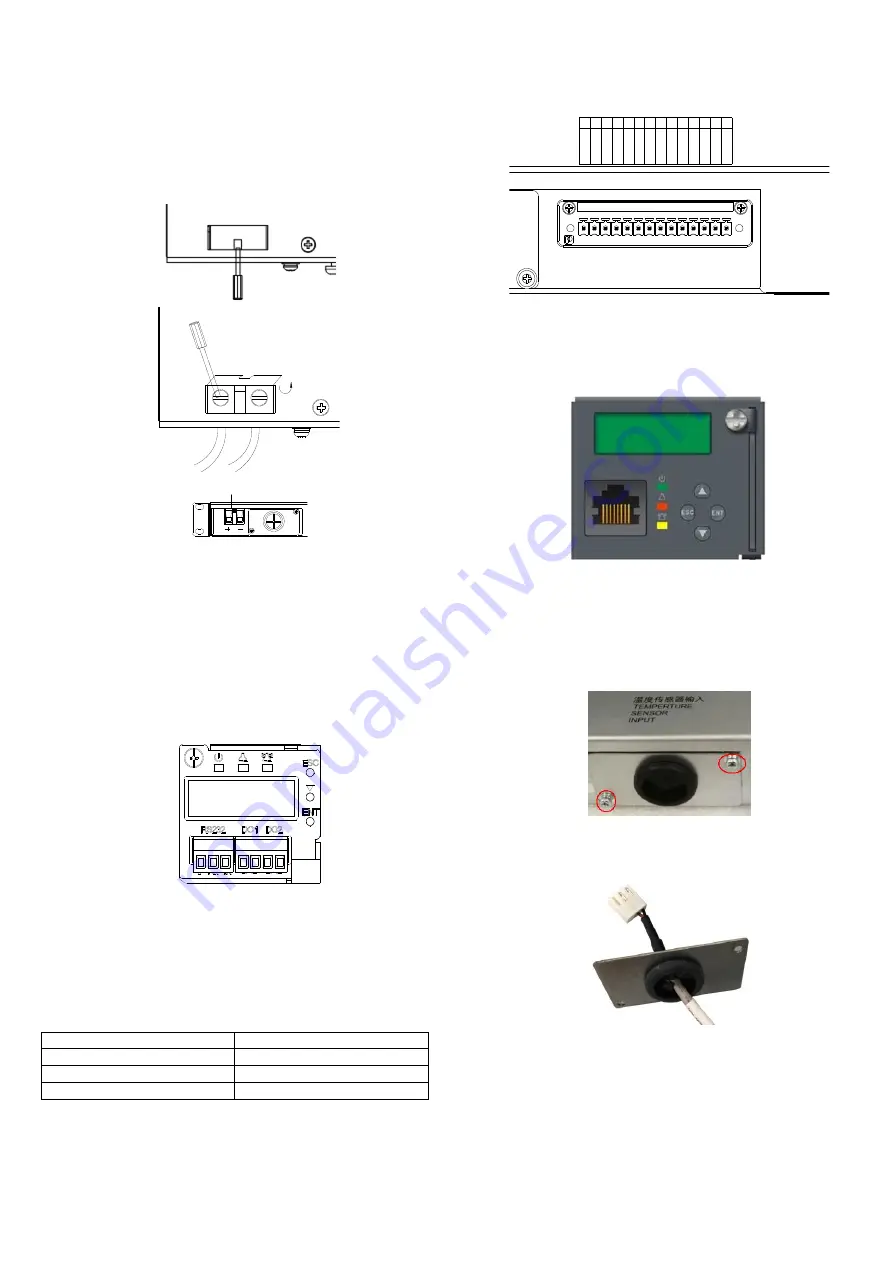
Connecting Ethernet port of M831A controller
The front panel of M831A is configured with an Ethernet port. When wiring, just insert the
network cable into the Ethernet port, as shown in Figure 2-13 (Users need to prepare
network cable themselves).
Figure 2-13 Illutration of M831A controller front panel
2.4.6 Connecting Temperature Compensation Cable
For NetSure 2100 A31-S2 configuration, the corresponding controller is M225S, and a
battery temperature compensation cable (Temp. cable for short) is configured. Take out
the Temp. cable from the accessory at the site and connect the cable as follows.
1. Loosen the two screws fixing the panel at the rear of the subrack, and use a knife to cut
along the cross center of the rubber ring, as shown in Figure 2-14.
Figure 2-14 Lossening the fixing screw
2. Lead the white terminal of Temp. cable through the rubber ring, as shown in
Figure 2-15.
Figure 2-15 Leading the cable through rubber ring
3. Pull out the terminal labeled ‘Temp’ fromt the subrack power supply, as shown in
Figure 2-16.


