10.7 Flow Sensor
WARNING! Arc flash and electric shock hazard. Open all local and remote electric power supply disconnect
switches, verify with a voltmeter that power is Off, and wear appropriate, OSHA approved personal protective
equipment (PPE) per NFPA 70E before working within the electric control enclosure. Failure to comply can
cause serious injury or death. Customer must provide earth ground to unit, per NEC, CEC, and local codes,
as applicable. Before proceeding with installation, read all instructions, verify that all the parts are included,
and check the nameplate to be sure the voltage matches available utility power. The Liebert® controller does
not isolate power from the unit, even in the Unit Off mode. Some internal components require and receive
power even during the Unit Off mode of the controller. The factory supplied, optional disconnect switch is
inside the unit. The line side of this switch contains live high voltage. The only way to ensure that there is NO
voltage inside the unit is to install and open a remote disconnect switch. Refer to unit electrical schematic.
Follow all local codes.
WARNING! Risk of contact with high speed rotating fan blades. Can cause serious injury or death. Open all
local and remote electric power supply disconnect switches, verify with a voltmeter that power is off, and
verify that all fan blades have stopped rotating before working in the unit cabinet or on the fan assembly. If
control voltage is applied, the fan motor can restart without warning after a power failure. Do not operate the
unit with any or all cabinet panels removed.
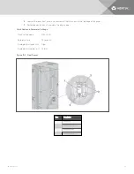
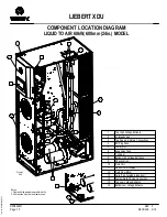
Fluid flow is sensed and reported to the unit control by an ultrasonic flow sensor. The sensor is clamped to the unit piping
without penetrating the pipe or obstructing the flow.
To replace the flow sensor:
1.
Shut off all power to the unit by opening the main disconnect switch on the electrical panel on the front of the
Liebert® XDU.
2.
Open the display door and remove the high voltage deadfront.
3.
Remove the six fan fuses.
4. Remove the two screws from the top of the lower front panel. Remove the panel and set aside.
5.
Open the fan panel assembly using the quarter-turn latches.
6. Disconnect the flow sensor cable.
7.
Unscrew the two sensor mounting screws and remove the sensor.
8.
Attach the sensor cable to the new flow sensor.
9. Replace the electric panel deadfront and restore power to the unit.
10. Program the flow sensor quick setting code and parameters using the instructions provided with the sensor.
(See Figure 10.3 on the facing page)
11. Shut off all power to the unit by opening the main disconnect switch on the electrical panel on the front of the
Liebert® XDU.
12. Disconnect the flow sensor cable.
13. Attach the new flow sensor to the mounting bracket with the two screws.
14. Attach the sensor cable to the flow sensor.
15. Re-install the six fan fuses.
16. Replace the electrical panel deadfront.
17. Close the fan panel assembly using the quarter-turn latches.
Vertiv | XDU™ Liquid to Air Heat Exchanger for Chip Cooling
46
Summary of Contents for Liebert XDU 060
Page 1: ...Liebert XDU Liquid to Air Heat Exchanger for Chip Cooling Installer User Guide 600 mm Wide ...
Page 10: ...Vertiv XDU Liquid to Air Heat Exchanger for Chip Cooling 6 This page intentionally left blank ...
Page 38: ...Vertiv XDU Liquid to Air Heat Exchanger for Chip Cooling 34 ...
Page 74: ...Vertiv XDU Liquid to Air Heat Exchanger for Chip Cooling ...


