ECLECTRICAL INSTALLATION
User Manual 10H52246UM60 - Rev. 1 - 01/2017
25
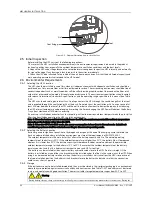
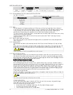
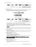
The RCCB symbols are shown in Figure 3-1.
Figure 3-1
RCCB symbols
The UPS has an internal EMC filter, therefore the protective earth cable leakage current is 0 ~ 1000mA. We
recommend verifying the RCD sensitivity of the upstream input distribution and the downstream distribution (to the
load).
External battery
The BCB is used to protect the external battery. The UPS may be supplied with an optional BCB box, which provides
over-current and short circuit protection and automatic tripping functions for the external battery. The rated
voltage of the BCB is 500Vdc, and its DC breaking current is 20kA.
This BCB is important for the battery maintenance, and is generally installed near the battery.
System output
The UPS output must be fitted with a protection device. This device must differ from the input distribution
protection switch and be able to provide overload protection (refer to Table 11-6 and Table 11-7).
3.1.10
Power Cable Connection Procedure
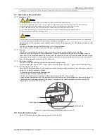
See para. 2.7.3
Cable Access Mode
for information on the UPS cable access mode
Connection terminal and cable routing method
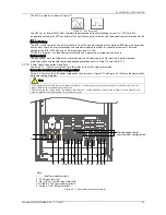
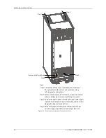
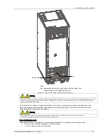
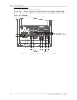
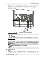
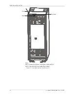
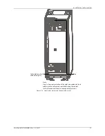
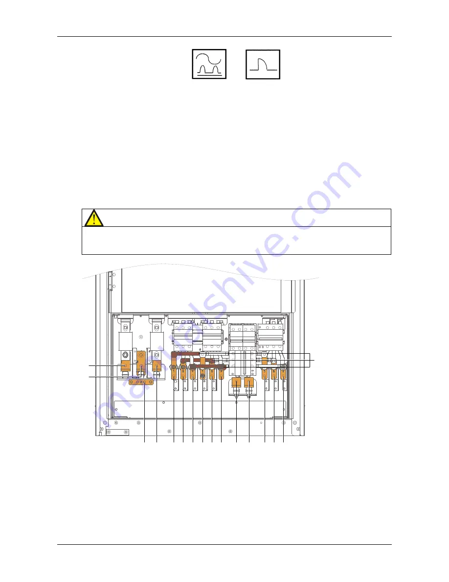
Figure 3-2 illustrates the UPS power cable connection terminals. Figure 3-3 and Figure 3-4 illustrate the power cable
entry and routing methods.
Note
1. The power cables should be routed through conduits or cable troughs to prevent damage due to mechanical stress and
reduce EMI into the surrounding environment.
2. When routing the cables inside the cabinets, they must be secured and fixed as illustrated in Figure 3-3 and Figure 3-4, in
order to prevent cable damage due to mechanical stress.
Note:
1. +, -, N: battery input terminals
2. PE: PE input terminal
3. mA, mB, mC: rectifier input terminals
4. bA, bB, bC, N: bypass input terminals
5. oA, oB, oC, oN: output terminals
+
mA mB mC bA bB bC
N
oN
oA oB oC
N
-
PE
Shorting copper bar of
common input configuration
Figure 3-2 Power cable connection terminals


