


38 Chapter 4 Operations
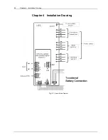
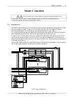
5.1.1 Split-Bypass Input
Fig.
5-1 illustrates the Liebert APM in what is known as the split-bypass configuration, i.e. the bypass uses a
separate AC source. In this configuration, the static bypass and maintenance bypass share the same independent
bypass power supply and connect to the power supply through a separate switch. Where a separate power source is
not available, the bypass and rectifier input supply connections are linked : the dotted lines represents the link
between
mA-mB-mC-mN and bA-bB-bC-bN (see fig
Fig.
4-10
). The unit is shipped with the links installed
There is one manual bypass (maintenance bypass) for entire UPS Rack System.
5.1.2 Static Transfer Switch
The circuit blocks labeled Static Switch in Fig.
4-1 contain electronically controlled switching circuits that enable the
critical load to be connected to either the inverter output or to a bypass power source via the static bypass line.
During normal system operation the load is connected to the inverter; but in the event of a UPS overload or inverter
failure, the load is automatically transferred to the static bypass line.
To provide a clean (seamless) load transfer between the inverter output and static bypass line, the inverter output and
bypass supply must be fully synchronized during normal operating conditions. This is achieved through the inverter
control electronics, which makes the inverter frequency track that of the static bypass supply, provided that the
bypass remains within an acceptable frequency window.
A manually controlled maintenance bypass supply is incorporated into the UPS design. It enables the critical load to
be powered from the utility (bypass) supply while the UPS is shut down for routine maintenance.
Note
When the UPS is operating in bypass mode or on maintenance bypass, the connected electrical load is not protected from
power failures or surges and sags.
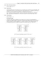
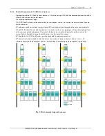
5.2 1+N Parallel System
Several “single unit” UPS Rack Systems may constitute a “1+N” system, where up to four single units operate
together for the purpose of providing additional power or reliability or both. The load is equally shared between any
paralleled UPSs.
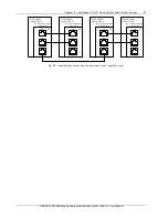
In addition, 1+N groups may be configured as “distributed redundant” systems. Each UPS Rack System has
independent outputs that nevertheless are synchronized through a Load Bus Synchronizer (LBS) so that critical loads
can be seamlessly transferred from one UPS Rack System or Parallel System to another.
See
4.3 Operating Mode
for more information.
5.2.1 Features Of Parallel System
1. The hardware and firmware of single UPS Rack System units is completely compatible with the requirements of a
parallel system. Parallel configuration can be achieved merely through settings in configuration software and
connecting the parallel control signal cables. The parameters settings for the UPS Rack Systems in parallel system
shall be consistent. .
2. Parallel control cables are connected in a ring, providing both performance and redundancy. Dual-bus control
cables are connected between any two UPS modules of each bus. The intelligent paralleling logic provides the user
with maximum flexibility. For example, shutting down or starting up UPS modules in a parallel system can be done in
any sequence. Transfers between Normal and Bypass modes of operation are synchronized and self–recovering e.g.
following overloads and their clearance.
3. The total load of the parallel system can be queried from each module’s LCD.
Summary of Contents for Liebert APM
Page 4: ......


