Installation Drawings
Vertiv
| Liebert
®
EXM
™
Parallel Cabinet User Manual |
16
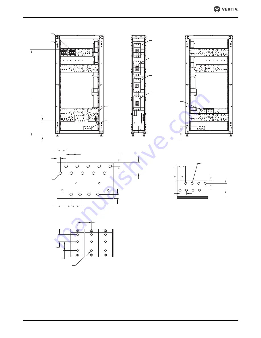
Figure 4
Main components—300mm 1+1 Liebert EXM Parallel Cabinet
Neutral
Busbar
TB2
(See Detail A)
TB3
(See Detail A)
NOTES
1. All dimensions are in inches (mm).
2. Control wiring and power wiring must be run in separate conduits.
3. All wiring is to be in accordance with national and local electrical codes.
4. If maintenance bypass cabinet is attached to UPS, Vertiv
will supply the interconnection cables.
MOB1
MOB2
MIB
MBB
67.8"
(1721mm)
12"
(305mm)
7.5"
(191mm)
1.8" (46mm)
0.65" (17mm)
0.65"
(17mm)
Ø 0.56"
(14mm)
14 Places
2.8"
(71mm)
2.2" (56mm)
8 Places
0.79"
(20mm)
0.79"
(20mm)
1.75" (44mm)
3 Places
1.75"
(44mm)
2.1"
(53mm)
1.6"
(41mm)
1.3"
(33mm)
6 Places
Ø 0.44" (11mm)
8 Places
0.59" (15mm)
1.3" (33mm)
2.7"
(69mm)
1.38"
(35mm)
Ø 0.38" (9.7mm)
9 Places
EXM16015
Rev. 1
TB5
(See Detail A)
DETAIL A
RIGHT SIDE
Panel Removed
FRONT VIEW
Door Removed
LEFT SIDE VIEW
Panel Removed
Ground
Busbar
GROUND BUSBAR
NEUTRAL BUSBAR


