MSS
Installation Procedure
User Manual 10H52252UMA0 - Rev. 2 - 09/2019
25
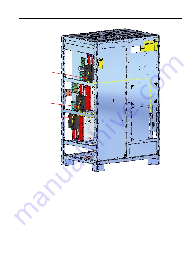
Figure 1-23 MSS CHASSIS bypass input left; rear view BFP wiring must pass through the CTs
WIRE 4 TO PHASE "U"
WIRE 5 TO PHASE "V"
WIRE 6 TO PHASE "W"
CB2
FRONT
Page 1: ...MSS for EXL S1 User Manual...
Page 2: ...MSS for EXL S1 1000 2000 3000 4000 5000A Main Static Switch USER MANUAL 10H52252UMA0 rev 2...
Page 3: ...or similar methods even of parts are reserved Offenders will be liable for damages All rights including rights created by patent grant or registration of utility model or design are reserved Delivery...
Page 4: ...NFIGURATION 53 3 1 Modbus Customer Information 54 3 2 Register Map 54 4 OPERATING PRINCIPLE 55 5 OPERATION CONTROL AND DISPLAY PANEL OF THE MSS 58 5 1 Introduction 58 5 2 MSS Operator Panel Interface...
Page 5: ...JURY FROM ACCIDENTAL ELECTRICAL ARCS REMOVE RINGS WATCHES AND ALL METAL OBJECTS ONLY USE TOOLS WITH INSULATED HANDLES WEAR RUBBER GLOVES NOTE REMOVE THE FUSES OF THE FANS BEFORE OPENING THE FAN COVERS...
Page 6: ...s and the MSS in centralized parallel system must be installed in a cool dry clean and well ventilated environment in which the mounting floor is flat and even and the ambient environmental parameters...
Page 7: ...able 1 Centralized parallel system for cabinet composition The TCE cabinet is provided only in the configuration 2000 3000 4000 5000A Figure 1 1 Centralized parallel system installation diagram Produc...
Page 8: ...MSS Installation Procedure User Manual 10H52252UMA0 Rev 2 09 2019 7 Figure 1 2 1000 MSS front and outline drawing top view and base view FRONT VIEW FRONT VIEW...
Page 9: ...Installation Procedure MSS 8 User Manual 10H52252UMA0 Rev 2 09 2019 Figure 1 3 2000 3000 4000 5000A MSS front and outline drawing top view and base view FRONT VIEW FRONT VIEW...
Page 10: ...ev 2 09 2019 9 To allow correct air flow for the cooling system leave a minimum distance of 500mm between the top of the cabinet and the ceiling of the installation area Figure 1 4 1000A MSS CHASSIS f...
Page 11: ...9 To allow correct air flow for the cooling system leave a minimum distance of 500mm between the top of the cabinet and the ceiling of the installation area Figure 1 5 2000 3000 4000 5000A MSS CHASSIS...
Page 12: ...ated surface weight loading kg cm2 of any handling equipment MSS and optional cabinets battery cabinets top cable entry cabinets etc can be handled by means of a forklift or similar equipment For oper...
Page 13: ...connection RIGHT Note When selecting the power cables for side entry to a module located on a solid floor consideration must be given to the minimum permissible radius of the proposed cables to ensur...
Page 14: ...e torque as per the following table Table 2 Connections for MSS TCE Customer cabinets Connections type Grease type P N 10H46591 Tightening torque Nm 20 Screw type Busbar type Cu busbar on Al heatsink...
Page 15: ...Installation Procedure MSS 14 User Manual 10H52252UMA0 Rev 2 09 2019 Figure 1 6 MSS 2000 3000 4000 5000A TCE cabinets front view...
Page 16: ...MSS Installation Procedure User Manual 10H52252UMA0 Rev 2 09 2019 15 Figure 1 7 MSS 2000 3000 4000 5000A TCE cabinets front and connections view CUSTOMER CONNECTIONS CUSTOMER CONNECTIONS...
Page 17: ...Procedure MSS 16 User Manual 10H52252UMA0 Rev 2 09 2019 Figure 1 8 2000 3000 4000 5000A MSS Side view points of connection TCE cabinets MSS Figure 1 9 2000 3000 4000 5000A MSS points of connection TCE...
Page 18: ...Procedure User Manual 10H52252UMA0 Rev 2 09 2019 17 Figure 1 10 2000 3000 4000 5000A TCE cabinets left front and outline drawing Figure 1 11 2000 3000 4000 5000A TCE cabinets left connection view TOP...
Page 19: ...dure MSS 18 User Manual 10H52252UMA0 Rev 2 09 2019 Figure 1 12 2000 3000 4000 5000A TCE cabinets right front and outline drawing Figure 1 13 2000 3000 4000 5000A TCE cabinets right connection view TOP...
Page 20: ...MSS Installation Procedure User Manual 10H52252UMA0 Rev 2 09 2019 19 1 3 5 MSS CHASSIS 1000 A I O Busbar Connection Figure 1 14 MSS CHASSIS 1000 A Busbar connections FRONT VIEW FRONT VIEW...
Page 21: ...3 6 MSS CHASSIS 2000 3000 4000 5000A I O Busbar Connection MSS CHASSIS may be configured with the bypass INPUT on the left side of the cabinet and OUTPUT on the right side or vice versa 1 3 6 1 Bypas...
Page 22: ...igures represent the bypass INPUT left concerning _ Busbar connection Figure 1 16 Figure 1 17 Figure 1 18 _ Backfeed protection CTs sensor Figure 1 19 Figure 1 20 Figure 1 21 _ Backfeed protection wir...
Page 23: ...2252UMA0 Rev 2 09 2019 Figure 1 17 MSS CHASSIS bypass input left output right side view Note THE LENGTH OF THE BUSBARS IS AT THE DISCRETION OF THE CUSTOMER Figure 1 18 MSS CHASSIS three phases and neu...
Page 24: ...n Procedure User Manual 10H52252UMA0 Rev 2 09 2019 23 Figure 1 19 MSS CHASSIS bypass input left left side CTs position Figure 1 20 MSS CHASSIS bypass input left phase U V CT position PHASE U PHASE V P...
Page 25: ...ypass input left phase W CTs position Note The CT of phase W is rotated 180 compared to phase U and V CTs see yellow marks in Figure MOUNTING POSITION the recommended mounting is vertical with the gap...
Page 26: ...ation Procedure User Manual 10H52252UMA0 Rev 2 09 2019 25 Figure 1 23 MSS CHASSIS bypass input left rear view BFP wiring must pass through the CTs WIRE 4 TO PHASE U WIRE 5 TO PHASE V WIRE 6 TO PHASE W...
Page 27: ...26 User Manual 10H52252UMA0 Rev 2 09 2019 1 3 6 2 Bypass Input Right Output Left MSS CHASSIS configured with bypass INPUT on the right side of the cabinet and OUTPUT on the left side Figure 1 24 MSS C...
Page 28: ...INPUT right concerning _ Busbar connection Figure 1 25 Figure 1 26 Figure 1 18 _ Backfeed protection CTs sensor Figure 1 27 Figure 1 28 _ Backfeed protection wiring Figure 1 22 Figure 1 30 Figure 1 25...
Page 29: ...dure MSS 28 User Manual 10H52252UMA0 Rev 2 09 2019 Figure 1 27 MSS CHASSIS bypass input right right side CTs position Figure 1 28 MSS CHASSIS bypass input right phase U V W CTs position PHASE V PHASE...
Page 30: ...Procedure User Manual 10H52252UMA0 Rev 2 09 2019 29 Figure 1 29 MSS CHASSIS 2000 3000A bypass input right rear view BFP wiring must pass through the CTs CB2 FRONT WIRE 4 TO PHASE U WIRE 5 TO PHASE V W...
Page 31: ...ocedure MSS 30 User Manual 10H52252UMA0 Rev 2 09 2019 Figure 1 30 MSS CHASSIS 4000 5000A bypass input right rear view BFP wiring must pass through the CTs WIRE 4 TO PHASE U WIRE 5 TO PHASE V WIRE 6 TO...
Page 32: ...ure 1 31 MSS CHASSIS bypass input left right BFP wiring with CTs electrical diagrams 1 3 7 MSS CHASSIS 1000 2000 3000 4000 5000A Remote Display Panel On MSS CHASSIS version the display panel may work...
Page 33: ...252UMA0 Rev 2 09 2019 NOTE at least one of the four corners where the display is connected to the cubicle must be not painted to warranty grounding Figure 1 33 MSS CHASSIS fixing dimensions display pa...
Page 34: ...BYPASS LINE QS2 UPS 2 1 1 MSS Single Wire Diagram TCE Cabinets The single wire diagram of the MSS TCE cabinets is a switchless version external circuit breakers QS2 QS5 QS6 QS7 are not included in MS...
Page 35: ...input of MSS TCE cabinets and the MSS rectifier input of the MSS parallel system use split bypass configuration or common input configuration Regardless of the configuration the maintenance bypass of...
Page 36: ...es based on a cable cross section of 240 mm2 2 1 6 Connecting Terminal The MSS power cables are connected to the copper bar as shown in Figure 2 2 and Figure 2 3 2 1 7 Power Cable Connection Steps of...
Page 37: ...o reach the MSS connection busbars Steps are as follows 1 Route power cable into the cabinet 2 As shown in 3 Figure 2 3 if using top cable entry method you can open holes on top of the cabinet for cab...
Page 38: ...O FOLLOW ADEQUATE EARTHING PROCEDURES CAN RESULT IN ELECTRIC SHOCK HAZARD TO PERSONNEL OR THE RISK OF FIRE SHOULD AN EARTH FAULT OCCUR CONNECTION OF THE EARTH CABLE AND THE NEUTRAL WIRE MUST COMPLY WI...
Page 39: ...omer installs external protection devices at the installation site These must be installed near the unit and labeled as the line power separation device for the UPS see IEC EN 62040 1 A1 2013 WARNING...
Page 40: ...supplied from the bypass via the Static Bypass Switch the isolated sources are connected in parallel A case by case analysis should be made as to whether any resulting imbalance between the currents...
Page 41: ...parallel MSS connection X20 RJ 45 Interface for synchronization with external signal XT1 2 pole screw connector for backfeed output contact XP10 EPO connector XP11 INPUT connector XP12 OUTPUT connect...
Page 42: ...iv applications The interface is SELV isolated from UPS primary circuits 2 3 5 Ethernet RJ 45 Interface for Service and Placement into Service X9 This interface is a 10 100 MBit auto negotiation full...
Page 43: ...ONTACTS DO NOT USE VOLTAGES SUPPLIED BY EXTERNAL POWER SUPPLY The interface is SELV isolated from UPS primary circuits WARNING THIS INTERFACE AND ITS FUNCTION ARE FOR USE BY AUTHORIZED VERTIV SERVICE...
Page 44: ...These cables are connected between the modules to pass control signals which govern module synchronization load sharing battery charge current sharing in a common battery installation load transfer o...
Page 45: ...s shown in Figure 2 7 and Figure 2 8 taking care to respect the phase sequence for the connection points Figure 2 7 Connection kit between UPS and MSS schematic diagram Figure 2 8 Connection between M...
Page 46: ...T ANY CABLE TO IT The interface is SELV isolated from UPS primary circuits 2 3 10 Connector for Backfeed Status Output XT1 One of the output contacts can be programmed for backfeed protection function...
Page 47: ...cy Stop switch To perform a remote emergency power off it is necessary to connect an emergency stop button to the UPS via a twisted shielded cable not exceeding 20 m in length The switch must be CLOSE...
Page 48: ...tomer selects the OR function UPS will enter EPO condition when one of the two inputs or both will activate This happens when one of the two lines is in short circuit and the other is functioning prop...
Page 49: ...is from 0 5 to 1mm2 2 3 13 Circuit Breakers Customers should provide circuit breakers that are correctly sized to withstand the nominal currents of the system Attention should be paid to tuning the s...
Page 50: ...nector will be connected to the customer plant 18 wire connector suitable for 250V signals Functional insulation between pins and reinforced insulation between XP10 and XP11 is required Type MSTBVA 2...
Page 51: ...rder to operate correctly the MSS requires the current measurement from the customer s mains supply system The MSS system output measurement is derived by using three sensors one for each rating which...
Page 52: ...Modbus over IP configuration User Manual 10H52252UMA0 Rev 2 09 2019 51 Figure 2 14 below shows the position of the current sensors in the system Figure 2 15 Customer distribution system output XT 1 6...
Page 53: ...o the terminal block For this reason the MSS is fitted with an internal terminal block X9A X9B which can be used to short circuit the CT when replacing the electronic control boards Apply the followin...
Page 54: ...About2 window by clicking on the top right Model button In this example the IP address is 10 50 55 45 Now open a web browser in the same network and enter the IP address The configuration screen will...
Page 55: ...rds which can be read out over Modbus This can be used to identify the slave against the master beyond its slave address among other things Enter a decimal word into each register and click Apply to s...
Page 56: ...d parallel system In the centralized parallel system the MSS TCE cabinets act as the bypass for the MSS parallel system and provide the backup power supply channel for the load The system will transfe...
Page 57: ...input failure the load will be automatically transferred onto the MSS s inverter regardless of the percentage rate 4 1 4 Short Circuit Control Logic As soon as an MSS s inverter detects the current li...
Page 58: ...THE LOAD IS POWERED BY BYPASS OR MAINTENANCE BYPASS THE QUALITY OF THIS POWER SUPPLY WILL BE UNCERTAIN CAUTION IF THE INPUT DISTRIBUTION DOES NOT HAVE AUTOMATIC CIRCUIT BREAKERS THE OUTPUT BUS AND THE...
Page 59: ...sing the LCD screen users can control the operation of the MSS TCE cabinets and check parameters status battery status as well as records of events and alarms of the MSS TCE cabinets The EPO button pr...
Page 60: ...display panel of the MSS User Manual 10H52252UMA0 Rev 2 09 2019 59 5 2 MSS Operator Panel Interface This document contains the 80 eXL EXL S1 MSS Operator Interface Panel description 5 2 1 Main Page F...
Page 61: ...buttons is possible to a START Simultaneously start all UPS inverters and turn bypass static switch OFF If system conditions allow this operation b BYPASS Simultaneously stop all UPS inverters and tur...
Page 62: ...equires a confirmation to be carried out 5 3 3 MSS Stop When Out of Synchronization The condition Out of Synchronization is recognized by the specific measure Sync Angle Figure 5 6 The command to stop...
Page 63: ...UPSs The MSS waits until the Sync Angle approaches 0 to carry out the command without applying any holes in the commutation The operator can choose to wait for automatic transfer to take place or can...
Page 64: ...e MSS User Manual 10H52252UMA0 Rev 2 09 2019 63 5 3 4 MSS Stop Inhibition during Bypass Failure In the event of bypass failure the BYPASS command is disabled and a message indicating this is shown nex...
Page 65: ...0 Rev 2 09 2019 5 3 5 Load Not Compatible with System Power In the event that the MSS command is requested when the load is not compatible with the MSS rate the command is inhibited and a specific mes...
Page 66: ...buttons will be enabled during the MSS start up based on following logic During the MSS start up both commands are disabled if the MSS recognizes that the DC bus of at least one UPS is not charged If...
Page 67: ...ion can damage the MSS if the DC bus of at least one UPS is not charged and the UPS output breaker is closed Figure 5 15 5 4 MSS Page Each UPS belonging to the centralized parallel system has a dedica...
Page 68: ...side of the page the System Operating State is available including Operating Mode Indicates the mode selected Double Conversion Intelligent ECO Mode Intelligent Paralleling Operating Status Indicates...
Page 69: ...urns the UPS OFF depending on the load condition The intelligent paralleling mode can be enabled by pressing the Enable Intell Parall Mode button Figure 5 18 Once the option is activated it is possibl...
Page 70: ...urns OFF all UPS inverters and transfers the load to bypass The ECO option can be enabled by pressing the Enable Intell ECO Mode button Figure 5 20 Once the ECO option is activated it is possible to m...
Page 71: ...70 User Manual 10H52252UMA0 Rev 2 09 2019 5 6 Measures Page The Bypass and Load stages each have a dedicated measures page Figure 5 22 5 7 Warning Fault Page The Warning Fault page contains a detailed...
Page 72: ...MSS Operation control and display panel of the MSS User Manual 10H52252UMA0 Rev 2 09 2019 71 Figure 5 24...
Page 73: ...ONLY AFTER THE AUTHORIZED ENGINEER HAS CARRIED OUT THE FIRST POWER ON AND TEST 2 THE PARTS BEHIND THE INNER DOOR WHICH CAN ONLY BE OPENED USING TOOLS SHOULD NOT BE OPERATED BY USERS ONLY QUALIFIED MAI...
Page 74: ...seen by opening the front door with a key Figure 6 1 and Figure 6 2 show the positions of the following power switches The reference example shown below is 80 eXL EXL S1 Use the following key QS1 PRIM...
Page 75: ...G LABEL TO THE LOAD CONNECTION POINT 3 IT IS IMPORTANT TO RESPECT THE CORRECT POWER ON AND START UP PROCEDURES 6 2 1 Power on Check before power on 1 Open the front door of UPSs and ensure that the QS...
Page 76: ...n UPS uses traditional lead acid battery the system provides an equalizing charge optional function If the lead acid battery is used when the mains returns after an extended mains failure the voltage...
Page 77: ...6 User Manual 10H52252UMA0 Rev 2 09 2019 Figure 6 4 6 2 3 Transfer to UPS If you want to transfer load to UPS inverter press the UPS icon as shown in below figure to access the screen shown in Figure...
Page 78: ...ev 2 09 2019 77 Figure 6 6 6 3 Shutting down UPS 1 If you want to shut down the centralized parallel system supplied by UPS follow this procedure Check the MSS LDC as shown in Figure 6 7 Figure 6 7 1...
Page 79: ...6 8 2 This operation will close the UPS rectifier inverter and battery and the centralized parallel system supply power to load through the static bypass of the MSS bypass cabinet 3 The power flow di...
Page 80: ...respective switches 5 Close the doors of all UPS cabinets 6 3 1 Shutting down the MSS Centralized Parallel System To shut down the MSS centralized parallel system and load power off follow this proce...
Page 81: ...the 1000 A version 2 Select fuses according to the MSS rating see table below MSS RATING FUSE 1000A 1000A 660V 2000 3000A 3500A 660V 4000 5000A 5000A 660V 7 2 RTU MODBUS KIT Use this kit when you need...
Page 82: ...Tvj 125 C 10 ms A2 s 4 5 106 16 2 106 36 106 Itsm Tvj 125 C 10 ms A 30 57 85 Withstand rating1 kA 50 100 ECO Mode efficiency 98 Transfer time when in synchro ms Inverter to inverter 0 5 no break Rese...
Page 83: ...Up to 95 Max altitude above sea level without de rating m 1000 m for higher altitudes complies with IEC EN 62040 3 Note 1 Withstand rating upfront a prospective short circuit current Withstand values...
Page 84: ...trical and Electronic Equipment WEEE Directive 2002 96 CE The crossed out wheelie bin symbol on the right is placed on this product to encourage you to recycle wherever possible Please be environmenta...
Page 85: ...of Vertiv Co All other names and logos referred to are trade names trademarks or registered trademarks of their respective owners 2019 Vertiv Co All rights reserved Vertiv com Vertiv Infrastructure L...