background image

Vertiv | Liebert EXS 80kVA UPS | User Manual

60

UPS Operating Instructions

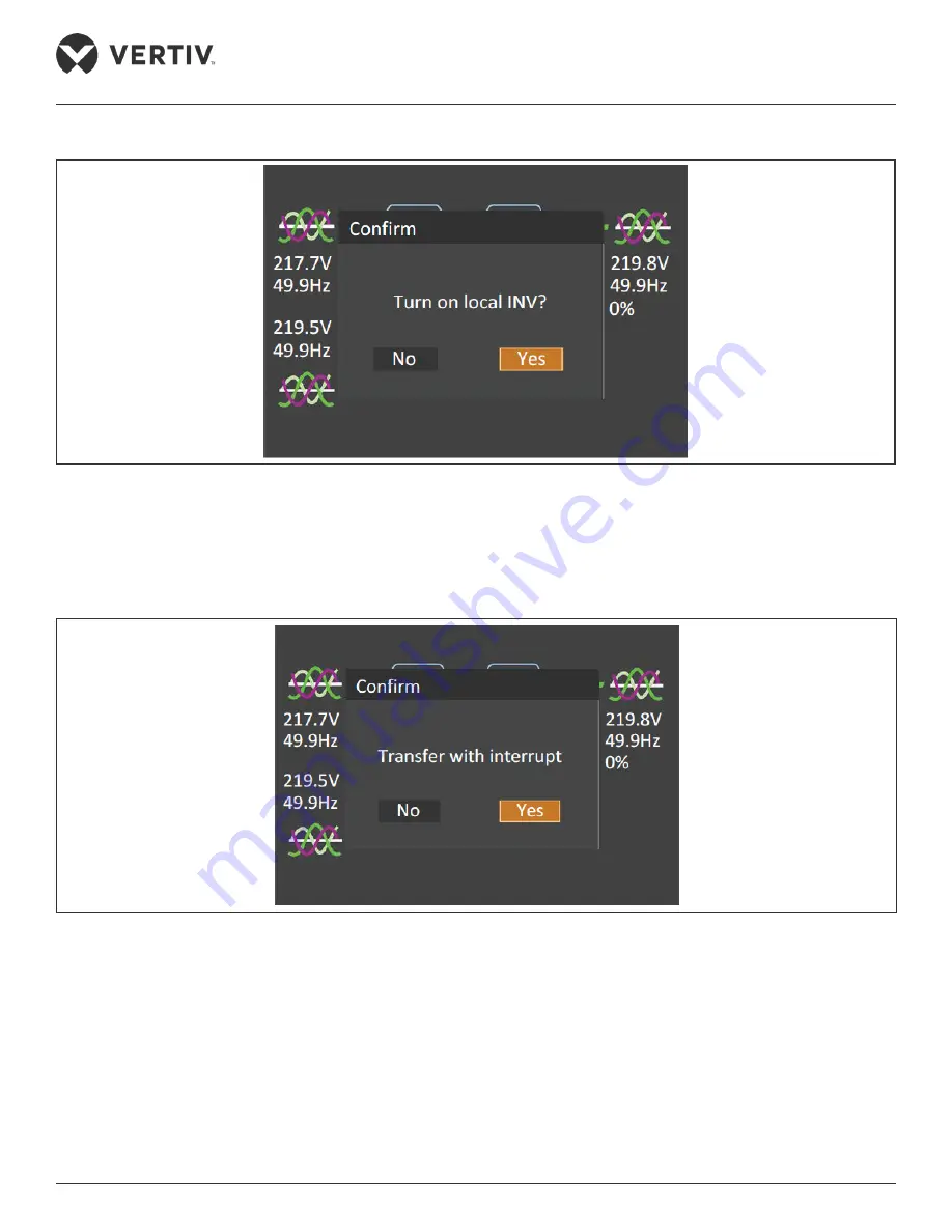
Figure 5-9 Switching the UPS ON

In Bypass mode, press the power button, and the LCD prompts a dialogue box shown in 

Figure 5-10

 if the alarm 

‘Bypass unable to trace’ appears. After selecting ‘YES’, the system will automatically transfer to Normal mode. 

Select ‘NOT’, the system still works in Bypass mode.

Figure 5-10 Transfer with Interruption

Summary of Contents for EXS 0080kTK16FN01000

Page 1: ...Liebert EXS 80kVA UPS User Manual...

Page 2: ...e specified in the contract all statements information and recommendations in this document are provided AS IS without warranties guarantees or representations of any kind either express or implied Th...

Page 3: ...best protocols that are standardized and help make maximum utilization of the resources at hand Helpful information related to the mainstream content also comes under the Note heading helping the use...

Page 4: ...be stored or remain de energized for a long period it must be placed in a dry and clean environment within specified temperature range 2 This product should be used in an appropriate operating environ...

Page 5: ...ions and all the safety points before operation When operating Vertiv products the operation personnel must observe the safety rules in the industry the general safety points and special safety instru...

Page 6: ...h connection is critical before connecting the input supply including both mains supply and battery 2 Earth leakage current is less than 2500 mA 3 Transient and steady state earth leakage currents whi...

Page 7: ...operating the battery the following should be observed Remove the watches rings and other metal objects Use the tools with insulation handle Wear rubber glove and shoes Avoid to place the tools and m...

Page 8: ...This page is intentionally left blank...

Page 9: ...n 5 1 2 5 Battery Circuit Breaker BCB 6 1 3 Parallel System 6 1 3 1 Parallel System Features 7 1 3 2 Parallel System Requirements 7 1 4 UPS States and Operating Modes 8 1 5 Battery Management 12 1 5 1...

Page 10: ...Drawings 24 Chapter 3 Electrical Installation 25 3 1 Wiring of Power Cable 25 3 1 1 System Configuration 25 3 1 2 Maximum Steady State AC and DC Currents 25 3 1 3 Recommended CSA Of UPS Cable 26 3 1...

Page 11: ...1 2 Power Switch 53 5 1 3 Check Before Start up 54 5 2 UPS Start up Procedures 55 5 2 1 Start up Procedures in Normal Mode 55 5 2 2 Start up Procedures in Battery Mode Battery Cold Start 57 5 3 Proced...

Page 12: ...apter 6 Parallel System and LBS System 75 6 1 General 75 6 2 Requirements 75 6 3 System Installation Procedures 75 6 3 1 Preliminary Checks 76 6 3 2 Cabinet Installation 76 6 3 3 Power Cables 77 6 3 4...

Page 13: ...ng LBS Cables 86 6 5 5 LBS Parameters Setting 87 6 5 6 LBS System Commissioning 87 Chapter 7 Communication 89 7 1 Installing Intelligent Card 89 7 1 1 Intelligent Card Port 89 7 1 2 Intelligent Card O...

Page 14: ...6 Battery Cabinet 108 Chapter 10 Specifications 111 10 1 Conformance and Standards 111 10 2 Environmental Characteristics 111 10 3 Mechanical Characteristics 112 10 4 Electrical Characteristics Input...

Page 15: ...nt products High power density little space occupied easy handling and assembly Capable of parallel system containing up to 4 units which enhances the reliability of power supply High input power fact...

Page 16: ...o convert the DC power supply into the three phase AC input voltage Figure 1 1 Block Diagram for Working Principle of UPS Single Module The working principle of single module UPS is as follows 1 The U...

Page 17: ...the battery 1 2 2 Bypass The loads can be supplied by the inverter or the bypass through the intelligent control of the Bypass Automatic Switch as shown in Figure 1 1 In normal circumstances the loads...

Page 18: ...UPS operator control and display panel will display corresponding alarm messages If the system uses split bypass configuration and the bypass is normal the system will transfer to bypass Mains Recover...

Page 19: ...ad returns to the inverter if the power is reduced to a value that can be sustained by the number of active modules in the system Maintenance Bypass The UPS has a second bypass circuit i e maintenance...

Page 20: ...to be disconnected the UPS control circuit sends a signal to the shunt tripping coil to trip the BCB It also has a magnetic trip facility for overload and short circuit protection 1 3 Parallel System...

Page 21: ...h the benefit of greater reliability The following requirements apply to ensure that all modules are utilised equally and that they comply with relevant wiring rules 1 All UPS modules must be of the s...

Page 22: ...de LBS Mode Normal Mode When the mains input is normal the load is supplied by the mains with voltage stabilizing and frequency stabilizing power after the rectifier and the inverter have been process...

Page 23: ...quate backup time The battery cold start function may also be used to start the UPS from the Battery mode provided it is fully charged in the event of a mains failure This means that the battery power...

Page 24: ...self as this may result in injury to personnel and or damage to equipment ECO Mode If ECO mode is selected all power switches and the battery switches are closed except for the maintenance bypass swit...

Page 25: ...an be composed of up to four UPS modules For the operation principle diagram of the parallel redundancy mode see Figure 6 1 Frequency Converter Mode The UPS can be programmed into frequency converter...

Page 26: ...loat charge When boost charge time exceeds the limit of Equalize Charge Protect Time Limit the charger forcibly transfers to float charge for protecting the battery 5 Float charge temperature compensa...

Page 27: ...ed the system updates the battery curve table The capacity self test command is valid only one time without any memory During the capacity self test if the battery maintenance requirement is met the s...

Page 28: ...scharge with full load for three remaining minutes The time can be configured from 3 min to 60 min EOD Protection When the battery voltage drops to the EOD voltage the battery converter automatically...

Page 29: ...oval of the commissioning engineer 3 In the case of any equipment or items not covered in this section refer to the specific mechanical and or electrical installation instructions provided with such i...

Page 30: ...or its weight It is recommended to use mechanical equipment such as an electric forklift to unload and move the equipment to the place closest to the installation site When using an electric forklift...

Page 31: ...sulated 2 Tools in Table 2 1 are for reference only please comply with the actual installation and connection requirements on site Table 2 1 Tools Name Drawing Name Drawing Electric hand drill Adjusta...

Page 32: ...er Manual 18 Mechanical Installation Name Drawing Name Drawing Electrician knife Cable tie Insulating tape Insulating gloves Crimping plier Heat shrinkable tube Insulated torque wrench Torque screwdri...

Page 33: ...under the guidance of authorized service engineer Steps 1 Use a cutting plier to cut the packing belt and remove the honeycomb board as shown in Figure 2 2 Figure 2 2 Removing Packing Belt and Honeyc...

Page 34: ...ve the fixed bottom part from the front of the cabinet Then loosen the fixing screws and remove the fixed bottom part from the rear of the cabinet see Figure 2 4 Figure 2 4 Removing Bottom Fixed Part...

Page 35: ...on and should be located on concrete or other nonflammable and flat surfaces The ambient environment should be free of conductive powder such as metallic powder sulfide sulfur dioxide graphite carbon...

Page 36: ...ting mode 2 6 3 Battery Room Batteries generate some amount of hydrogen and oxygen at the end of charge so the fresh air volume of the battery installation environment must meet the EN50272 2001 requi...

Page 37: ...capacity Refer to Table 10 3 for its weight 2 Due to its intensity the caster may not be valid on the uneven surface 3 The center of gravity of the UPS cabinet is high avoid falling over during the c...

Page 38: ...Vertiv Liebert EXS 80kVA UPS User Manual 24 Mechanical Installation 2 8 Installation Drawings Figure 2 6 Top Front Side Bottom View of the 80kVA UPS unit mm...

Page 39: ...differs from the UPS power ratings and input AC voltages provided that it meets the requirement of maximum input current including the maximum battery charge current see Table 3 1 UPS bypass and outp...

Page 40: ...EOD voltage of 1 6 V 100 load percentage 3 1 3 Recommended CSA Of UPS Cable The recommended CSA of the UPS cable is listed in Table 3 2 Table 3 2 Recommended CSA of the UPS Cable unit mm2 ambient temp...

Page 41: ...put PE cable output PE cable and external battery PE cable All the cabinets and cable troughs shall be grounded in accordance with local regulations The grounding wires shall be securely tied to preve...

Page 42: ...ethods Warning Selecting internal battery and external battery at the same time is prohibited The power cables should be connected firmly and correctly Add wire guard to the power cable to avoid unexp...

Page 43: ...he battery cables in the cabinet through the reserved cabling hole at top of the routing area Refer Figure 3 1 to connect power cables to corresponding terminals and fix PE cable to PE terminal To avo...

Page 44: ...terminal correctly and reliably Connection of system output Connect the system output cables between the output terminals oA oB oC N in the cabinet and the load Refer to Table 3 1 for the torque valu...

Page 45: ...pectively route the power cables and signal cables The shielding coat of signal cable must be reliably earthed Refer to 7 2 Connection Cables for Dry Contact Port for the definition of signal cables R...

Page 46: ...Vertiv Liebert EXS 80kVA UPS User Manual 32 This page is intentionally left blank...

Page 47: ...ndows message and UPS alarm list 4 1 Introduction The operator and display panel is located on the front panel of the UPS The operator and display panel allow the user to operate and monitor the UPS a...

Page 48: ...o different kinds of audible alarms as described in Table 4 2 Table 4 2 Description of Audible Alarm Sound Meaning Continuous beep This sound is generated in the event of a UPS fault condition such as...

Page 49: ...ser friendly menu oriented LCD it is possible to browse easily through the UPS input output load and battery parameters obtain information about the current UPS status and alarm messages as well as pe...

Page 50: ...for approximately 10 seconds as shown in Figure 4 4 Figure 4 4 Start up Screen 4 2 2 Flow Screen Once the UPS self test is complete the flow screen as shown in Figure 4 5 is displayed The flow screen...

Page 51: ...o switch the cursor to select the required submenu then press the key to confirm it 4 2 4 Submenu Screen The submenu screen contains the UPS parameters and item settings After accessing the submenu sc...

Page 52: ...Vertiv Liebert EXS 80kVA UPS User Manual 38 Operator Control and Display Panel Status page The Status page contains information about the Input Bypass Battery Output and Load See below...

Page 53: ...Vertiv Liebert EXS 80kVA UPS User Manual 39 Operator Control and Display Panel Settings Page The Settings page is used to access the Monitor and System settings See below...

Page 54: ...Operator Control and Display Panel Control Page The Control page is used to access the Clear faults Mute Unmute audible alarm etc functions See below Log Page The Log page is used to access a list of...

Page 55: ...Vertiv Liebert EXS 80kVA UPS User Manual 41 Operator Control and Display Panel About Page The About page contains information about the Product Run time and Efficiency See below...

Page 56: ...rtiv service engineers only Default Screen During the UPS operation if there are no alarms for two minutes the display will return to its default as shown in Figure 4 7 While the Default screen is dis...

Page 57: ...such as no battery charger failure is not met Turn on more UPS to carry current load The number of inverters already turned on is insufficient to carry the existing load The user is required to turn...

Page 58: ...rallel system Turn on local INV Turn on PARA INV Turn off UPS This prompt appears when you press the power button select one Turn to bypass Transfer sys to bypass Turn off UPS This prompt appears when...

Page 59: ...fier shutdown Input Undervoltage At least one phase main input voltage is within 132 V 176 V thus the load should be derated Excess Auto Retransfers The load remains on bypass power owing to excessive...

Page 60: ...ry is in boost charge mode and the load capacity is larger than 20 MonCAN Comms Abnormal Communication failure among internal monitoring board and inverter rectifier and bypass PowerCAN Comms Abnormal...

Page 61: ...will report this alarm Inverter Fault Inverter output voltage outside specifications Load transfers to bypass if bypass is available DC Bus Abnormal Shutdown DC bus voltage outside specifications Loa...

Page 62: ...t happened Check the battery voltage Control Power Fail The auxiliary power failure or power off Operation Invalid Maintenance bypass switch is closed when the parallel system is on inverter or output...

Page 63: ...tion maintenance bypass switch closed or DC bus or rectifier that is not ready Inverter Manual Off Power button on the operator control and display panel pressed manually to turn off the inverter Auto...

Page 64: ...lligent ECO mode enabled Intell ECO Mode Active Intelligent ECO mode activated Intell ECO Mode Demo Enabled Intelligent ECO demo mode enabled Intell ECO Mode Demo Active Intelligent ECO demo mode acti...

Page 65: ...Inhibit Trans to Inverter active The UPS will stay in bypass mode and inverter mode will be inhibitted Battery Test Stopped Battery test has been stopped manually For UPS installed with the optional...

Page 66: ...Vertiv Liebert EXS 80kVA UPS User Manual 52 This page is intentionally left blank...

Page 67: ...ated to all the operating steps refer to Chapter 4 Operator Control and Display Panel 2 During operation the buzzer alarm may be activated if so you can select the command of Mute Unmute audible alarm...

Page 68: ...there are no short circuits 2 Check that the batteries are properly installed the cables are correctly connected and that the positive and negative battery poles are correct 3 Measure the mains voltag...

Page 69: ...owing procedures to switch on the UPS when it is in fully switched off state 1 Open the front door of the UPS ensure that the internal maintenance bypass switch Q3 is off and that the input cables and...

Page 70: ...correct and then go back to the Flow page 5 Access the flow page press the power button and the LCD prompts a dialog box as shown in Figure 5 4 After selecting YES the inverter executes self check and...

Page 71: ...y battery cold start button for 2s see Figure 5 1 for its position Now the system is powered on and the startup screen is displayed Refer to 4 2 1 Start up Screen 25 seconds later the discharger execu...

Page 72: ...tery mode to Normal mode wait few seconds for the mains input to recover by closing the external power switch or switch Q1 After about ten seconds the rectifier automatically restarts and the inverter...

Page 73: ...is displayed select NO to shut down the UPS output Figure 5 8 Bypass Abnormal Interface 5 3 3 Transfer from Bypass Mode to Normal Mode In Bypass mode press the power button and the LCD prompts a dial...

Page 74: ...N In Bypass mode press the power button and the LCD prompts a dialogue box shown in Figure 5 10 if the alarm Bypass unable to trace appears After selecting YES the system will automatically transfer t...

Page 75: ...ffle to the left until it is in locked position then fasten the fixing screws Now the LCD displays Maint Switch Closed 3 Close the maintenance bypass switch Q3 Now the maintenance bypass parallels wit...

Page 76: ...ant to close the bypass switch before opening the maintenance bypass switch otherwise the power supply to the load will be interrupted 5 4 Battery Test Procedures The battery test function is disabled...

Page 77: ...up time battery discharge duration during AC input failure and the battery aging coefficient battery capacity percentage when compared to a new battery 4 Stop the test If required the test may be stop...

Page 78: ...ttery 2 Set the main input switch Q1 bypass input switch Q2 output switch Q5 and N line switch QN to off At this point all the internal power supplies are deactivated and the LCD screen is switched of...

Page 79: ...t Procedures After EPO After the UPS has been shut down through EPO or due to inverter overtemperature overload battery overvoltage and DC bus voltage clear the fault according to the alarm message di...

Page 80: ...default 10s During the Auto Restart delay the UPS will charge the battery to provide a safety margin for equipment shutdown if input power fails again 3 If the Auto Restart function is disabled you ca...

Page 81: ...see Figure 5 13 Figure 5 13 Monitor Interface 3 Press the key to highlight the language see Figure 5 14 Figure 5 14 Language Selection 4 Press the or key to select your required language then press th...

Page 82: ...the key several times to back to the main menu screen 5 11 Changing Current Date and Time Procedures for changing the system date and time 1 Access the main menu screen and press the or key to switch...

Page 83: ...e cursor to Monitor see Figure 5 17 Figure 5 17 Monitor Interface 3 Press the key and press the or key to highlight the date and time see Figure 5 18 Figure 5 18 Selection of Date and Time 4 Press the...

Page 84: ...g Date and Time 5 Press the key to confirm it and then press the key several times to back to the main menu screen 5 12 Setting Password 1 After switching on the UPS access the main menu screen and pr...

Page 85: ...Instructions 2 Press the key the interface shown in Figure 5 21 is displayed Figure 5 21 Inputting Password To change the password proceed as follows 1 Press the key to move the cursor to the Monitor...

Page 86: ...Operating Instructions 2 Press the key then press the key to select Change settings password see Figure 5 23 Figure 5 23 Changing Settings Password 3 Press the key the interface shown in Figure 5 24...

Page 87: ...rm at this point the system requests the user to enter a new password See Figure 5 25 Figure 5 25 Inputting New Password 5 After entering the new password press the key to confirm it at this point the...

Page 88: ...at this point system prompt a dialog box indicating that the password has been changed successfully see Figure 5 27 Figure 5 27 Password Changed Successfully 7 Press the key several times to go back t...

Page 89: ...system comprising of multiple parallel connected UPSs is equivalent to a large UPS system Nevertheless it provides increased system reliability To ensure equal utilization of all UPSs and compliance w...

Page 90: ...and hardware releases are consistent Warning To achieve coordinated operation of the modules in the parallel system it is required to configure each module separate ly using Vertiv setting software T...

Page 91: ...t transformers then these two transformers should share one grounding grid 6 3 4 Parallel Cables Shielded and double insulated parallel cables available in lengths of 5 m 10 m and 15 m must be interco...

Page 92: ...de dry contact signal which is normally open or normally closed The external EPO device can be composed of another control system which can disconnect UPS mains supply or bypass input Figure 6 3 EPO C...

Page 93: ...of the parallel cable is reliable and that the user load is not connected during power on 4 Measure the mains voltage and frequency and verify that they are correct 5 When the UPS is switched on the U...

Page 94: ...The rectifier runs in normal state for about 30 seconds after which the rectifier start up phase is complete Please confirm that the LCD displays bypass and main input normally and that the current l...

Page 95: ...f the UPSs is connected parallelly 2 During the parallel power on confirm that the system is working normally and then feed power to the load to void load power failure 6 4 4 Maintenance Bypass Proced...

Page 96: ...ead of the pure AC power from the inverter 6 Disconnect the main input switch Q1 bypass input switch Q2 output switch Q5 and N line switch QN of each UPS in turn At present all the internal power supp...

Page 97: ...ce personnel of Vertiv or under their guidance The following procedures are used to reintegrate a UPS module that has been previously isolated from the parallel system 1 The UPS internal cooling fan s...

Page 98: ...intenance work on it If the UPS is equipped with an external battery set the corresponding external battery switch to off 3 Disconnect the main input switch Q1 bypass input switch Q2 output switch Q5...

Page 99: ...utput of the two independent or parallel UPS systems One system is designated as the master the other is designated as the slave The operation modes of the parallel system comprise master and or slave...

Page 100: ...f single system Refer 3 1 Wiring of Power Cable The bypass and rectifier input supplies must use the same neutral line input terminal If the input has a current leakage protective device the current l...

Page 101: ...ure 6 7 Connection of Typical LBS System Parallel System 6 5 5 LBS Parameters Setting The parameters of LBS parameters must be set by Vertiv engineer through Vertiv setting software 6 5 6 LBS System C...

Page 102: ...Vertiv Liebert EXS 80kVA UPS User Manual 88 This page is intentionally left blank...

Page 103: ...t left side Remove the protective cover to install communication device options including SIC card IS UNITY DP card IS UNITY LIFE card and IS RELAY card Figure 7 1 Intelligent Card Installation 7 1 2...

Page 104: ...7 3 for the appearance of IN UNITY DP card Figure 7 3 IS UNITY DP Card For further description of the IS UNITY DP card refer to Liebert IntelliSlotTM Unity Card User Manual Web SNMP Modbus BACnet YDN2...

Page 105: ...edures Warning Some electron components in the intelligent card are static sensitive therefore do not touch the electron components or circuit in the intelligent card by hand or other conductive mater...

Page 106: ...and display panel is main menu screen setting monitor serial port 1 baudrate or serial port 2 baudrate 6 The path of main menu screen setting monitor UPS address is used to set the communication addre...

Page 107: ...and Pin3 shorted to enable this function Can configure input dry contact J13 1 3 GND_SELV 5 MOB On Generator Transfer to Inverter Inhibited External MIB External MBB Module Output Breaker default Batt...

Page 108: ...y Ground Fault Charger Shutdown ECO Inhibited Inverter Mode Preferred Start Battery Maintenance Self check Stop Battery Maintenance Self check Alarm Cleared Pin2 and Pin4 shorted to enable this functi...

Page 109: ...C Trigger EPO upon Pin2 and Pin4 opened 4 12V_EPO 6 12V_EPO Trigger EPO upon Pin6 and Pin8 shorted 8 REPO_NO J152 Battery BCB port 1 BCB_DRIVE BCB tripping drive normally 0V 12V tripping 2 BCB_STATUS...

Page 110: ...ll be effective if configurable input dry contact is configured as other functions the level triggering will be effective Activating the UPS EPO will close the rectifier inverter bypass and battery bu...

Page 111: ...essary to change the REPO switch state and manually switch on the UPS 3 REPO switch is only valid for the specified unit in parallel system We recommend using 0 82 mm2 0 33 mm2 signal cable 18 AWG 33...

Page 112: ...Vertiv Liebert EXS 80kVA UPS User Manual 98 This page is intentionally left blank...

Page 113: ...in continuous operation The higher the ambient temperature the shorter the fan life During the UPS operation it is important to check the condition of the fans regularly by confirming that they blow...

Page 114: ...onally important issue Batteries must be stored transported used and disposed in accordance with national and local legal requirements and all other criteria applicable to the treatment of hazardous w...

Page 115: ...is discharging If the AC mains supply is within normal limits the battery should not be discharged if you find that it is operating in Bypass mode determine the reason mains failure battery test oper...

Page 116: ...Vertiv Liebert EXS 80kVA UPS User Manual 102 This page is intentionally left blank...

Page 117: ...256 LBS cable 10 m EXS 0040kTH16FN01SL12 04113257 LBS cable 15 m UF LBS01 50 0235A04V LBS extension cable 50 m UF LBS01 150 0235A04Y LBS extension cable 150 m SIC card UF SNMP810 02351817 Option for i...

Page 118: ...red in 2 1 parallel system four communication cables are required in 3 1 parallel system EXS 0040kTH16FN01SL11 For N 1 parallel system N 1 communication cables 10 m are required EXS 0040kTH16FN01SL12...

Page 119: ...nnect up to eight temperature sensors IS UNITY DP card IS UNITY DP For further description of the IS UNITY LIFE card refer to Liebert IntelliSlotTM Unity Card User Manual Web SNMP Modbus BACnet YDN23...

Page 120: ...y against overdischarge and overcurrent and isolates the UPS and battery thereby reducing the risk at lowest for service personnel during the maintenance The box inside has connection bars for connect...

Page 121: ...board 5 Base plate 6 Current sensor to be installed when selecting battery ground fault kit 7 Wall mounted installation hole 8 Protective door 9 Cabling hole for confirming the cable size and opening...

Page 122: ...distance is 30 m and the UPS side of the shielding coat must be connected to the enclosure reliably Caution If the corresponding functions are not required just do not connect corresponding terminals...

Page 123: ...Manual 109 Options Table 9 8 Parameters of BCB Cabinet Dimensions H W D mm Weight kg CB CB instantaneous setting current 1600 600 850 130 560 180A 3P 1800 A Note This weight excludes the packaging Fig...

Page 124: ...Vertiv Liebert EXS 80kVA UPS User Manual 110 This page is intentionally left blank...

Page 125: ...2 Level 3 PFMF IEC EN62040 2 Level 4 Surge protection Meets IEC EN62040 2 live line to earth withstand level 4 4 kV withstand level 3 between live lines 2 kV Safety IEC EN62040 1 SPD test Meets ANSI...

Page 126: ...ype VRLA battery Battery cell Block 32 34 36 38 40 block at full load 26 28 30 block derated Max charge current A 25 Item Unit Rated Power kVA 80 kVA 380 400 415 Line voltage Input voltage range Vac 1...

Page 127: ...ynamic response recovery time ms 40 Frequency synchronization range Hz Rated frequency 3 Hz Configurable range 0 5 1 2 3 10 Frequency track rate Hz s 0 5 Hz s Configurable range 0 1 3 Hz s single UPS...

Page 128: ...Vertiv Liebert EXS 80kVA UPS User Manual 114 This page is intentionally left blank...

Page 129: ...be set from 0 to 9 The password length is 6 111111 System System configuration Single Parallel Parallel LBS configuration None LBS slave LBS master None System operation mode Normal Intelligent paral...

Page 130: ...oltage 120V 127V 220V 230V 240V Note related to system voltage level Equal to nominal output voltage Output Transfer Interrupt Time None 40 ms 60 ms 80 ms 100 ms None Excessive Auto Retransfers 1 10 5...

Page 131: ...0 00 Period test weekday Monday Sunday Sunday Low prewarning time 2 60 Min 5 Min Max discharge time 1 72 Hour 24 Hour Parallel UPS ID No 1 4 1 Requisite UPS Units 1 4 1 Redundant UPS Units 0 3 0 Sleep...

Page 132: ...Stop Battery Maint Test Alarm Reset Inhibit trans to inverter General Purpose Dry Contact J13 1 I N A onGen Inhibit trans to inverter Ext_MIB Ext MBB status MOB Battery GND Fault Charger Off Suspend...

Page 133: ...ge EPO Emergency Power Off I O Input Output LBS Load Bus Synchronizer LCD Liquid Crystal Display LED Light Emitting Diode MCB Miniature Circuit Breaker NMS Network Management System PE Protective Eart...

Page 134: ...Vertiv Liebert EXS 80kVA UPS User Manual 120 This page is intentionally left blank...

Page 135: ...cuit breaker o o o o o o Semiconductors o o o o o o Battery when applicable x o o o o o Insulation monitoring device when applicable N A N A N A N A N A N A This table is made following the regulation...

Page 136: ...Vertiv Liebert EXS 80kVA UPS User Manual 122 This page is intentionally left blank...

Page 137: ...to are trade names trademarks or registered trademarks of their respective owners While every precaution has been taken to ensure accuracy and completeness herein Vertiv Co assumes no responsibility...

Reviews: