background image

Connecting a music-on-hold (MOH) system

3

-

25

Chapter 3: Setting Up the Wave IP 500 Server

Wave Server Installation Guide

Connecting a music-on-hold (MOH) system 

A music-on-hold device plays prerecorded music or messages to callers—either from a tape or 
CD—when they are placed on hold or while being transferred. 

The Wave Server is compatible with most standard music-on-hold devices that connect via a 3.5 
mm stereo plug. If a cable is not provided, you must purchase one separately.

Note:  

Although a stereo cable is required, music on hold only plays in mono.

Caution:  

Always follow the instructions supplied by the manufacturer of your music-on-hold 

device when installing and connecting the device to avoid possible injury to yourself or damage 
to the equipment.

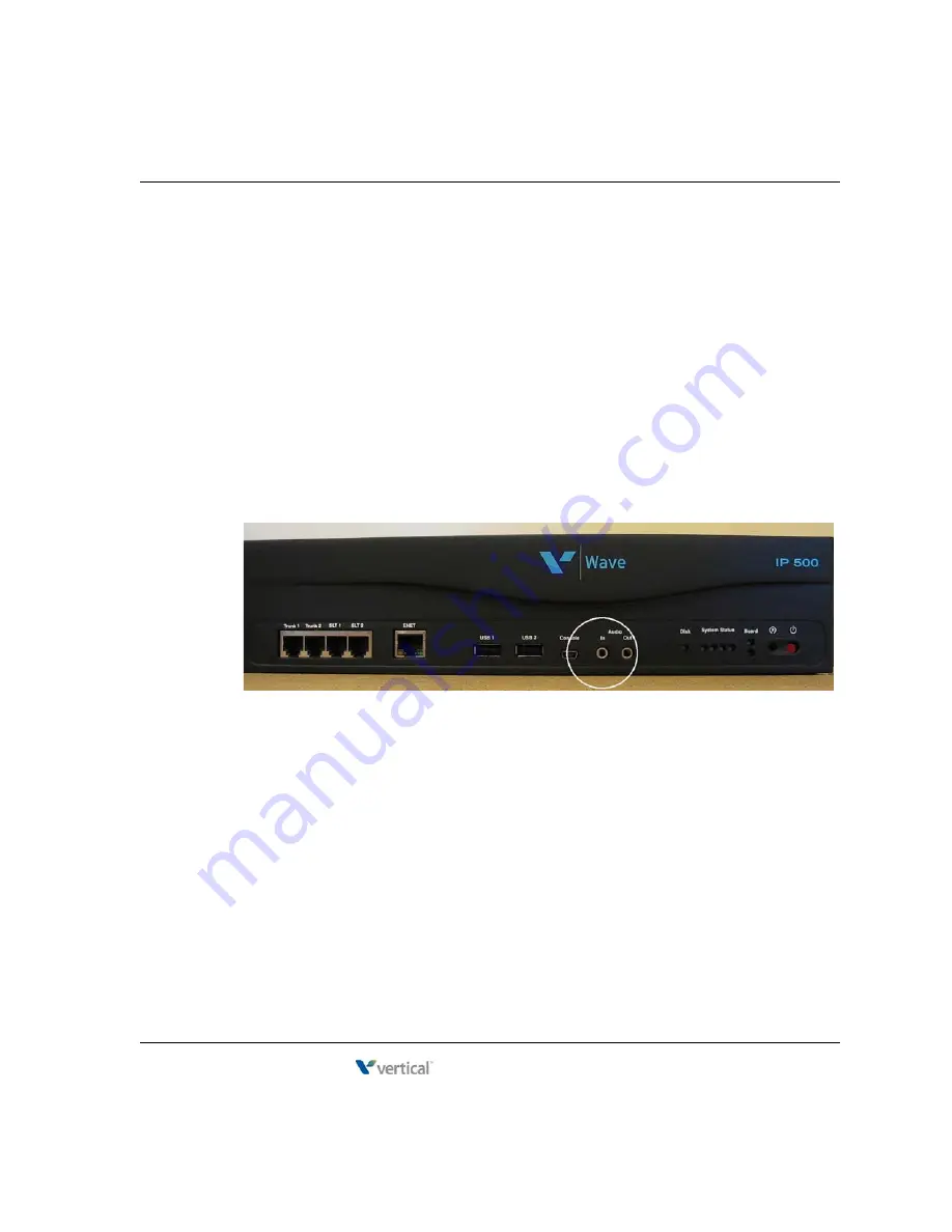
To connect a music-on-hold device:

1.

Locate the audio input port (labeled Audio In) on the ISC2.

2.

Connect the cable from your music-on-hold device to the port.

3.

Enable music on hold in the General Settings applet of the Global Administrator 
Management Console. See the 

Wave Global Administrator Guide

 for more information.


Release 4.0


June 20, 2013

Summary of Contents for WAVE IP 2500

Page 1: ...Wave Server Installation Guide Wave 4 0 Wave Server Installation Guide Release 4 0 June 20 2013 ...

Page 2: ...the accuracy or completeness of the content of this publication and specifically disclaims any implied warranty of merchantability or fitness for any particular purpose and shall not be liable for any loss of profit or any other commercial damage including but not limited to special incidental or consequential COPYRIGHT STATEMENT This publication contains proprietary and confidential information o...

Page 3: ...REVISED FOR THIS VERSION The following sections have been updated Wave license requirements Added the Wave ViewPoint Mobile license to the table of license types See page 8 5 ViewPoint PC requirements Added Windows 8 32 bit and 64 bit versions to list of supported operating systems updated minimum required NET version to NET 3 5 SP1 See page 9 4 Text in blue indicates an addition or change in this...

Page 4: ...Release 4 0 June 20 2013 ...

Page 5: ...this guide 1 2 Using Help 1 2 Conventions used in this guide 1 3 Special messages 1 3 Terms used 1 3 Type conventions 1 4 Related reading 1 4 Manuals 1 4 Quick Reference Guides 1 4 For more information 1 5 Support services 1 5 System security 1 5 Compliance statements 1 6 Federal Communication Commission FCC statement 1 6 Release 4 0 June 20 2013 ...

Page 6: ...er lifting 2 7 Chapter 3 Setting Up the Wave IP 500 Server About the Wave IP 500 Server 3 2 Wave IP 500 Server components 3 3 Power supply 3 5 Wave IP 500 Server expansion options 3 6 Mounting the Wave IP 500 Server 3 8 Rack mounting the Wave IP 500 Server 3 8 Wall mounting the Wave IP 500 Server 3 8 Table mounting the Wave IP 500 Server 3 10 Grounding the Wave IP 500 Server 3 11 Connecting the Wa...

Page 7: ... analog trunk module 3 20 Connecting the analog universal module 3 20 Connecting the digital station module 3 21 Connecting the external power supply for digital phones 3 21 Connecting the T1 module with serial interface 3 22 Connecting the T1 module without serial interface 3 23 Connecting the E1 EuroISDN module with serial interface 3 23 Connecting the Quad BRI module 3 24 Connecting a music on ...

Page 8: ...IP 2500 Server to your LAN 4 13 About the Ethernet ports on the Wave IP 2500 Server 4 13 Connecting to trunk and station ports on the ISC1 4 14 Power failover support 4 15 Installing expansion components 4 15 Installing EXUs on a Wave IP 2500 Server 4 16 Installing a Media Resource Module 4 17 Installing expansion modules and cards 4 19 About connecting modules and cards 4 20 About cable connectio...

Page 9: ...4 29 Connecting a paging system 4 29 Connecting a DSS Console 4 30 Chapter 5 Connecting to the Wave ISM from the administrator PC Obtaining all required HotFixes 5 1 Administrator PC requirements 5 2 Configuring the administrator PC 5 3 Connecting to the Wave ISM 5 5 Connecting to the Wave Server via your network 5 6 Connecting to the Wave ISM via a modem 5 10 Chapter 6 Using the Wave Installation...

Page 10: ... name of the Wave Server 7 8 Power cycling the Wave Server 7 12 Setting the dial in default IP address pool 7 14 Performing basic system configuration tasks 7 15 Entering basic system information 7 15 Setting the system date and time 7 19 Configuring the time service used by Wave ISM 7 20 Adding Wave ISM user and administrator accounts 7 21 Adding Wave ISM user accounts and passwords 7 21 Creating...

Page 11: ...icenses 8 8 Before your licenses are activated 8 9 The activation process 8 10 Activating your Wave licenses using one click activation 8 11 Activating your licenses using offline activation 8 13 Configuring the Wave ISM to save rather than open License files 8 17 Setting up a proxy server for license activation 8 17 Viewing the status of licenses on your system 8 19 Chapter 9 Installing ViewPoint...

Page 12: ...oint 9 10 Configuring the TAPI Service Provider 9 10 Configuring the Wave Contact Manager Assistant 9 11 Configuring the Archived Recording Browser 9 12 Synchronizing system clocks 9 12 Chapter 10 Installing the Wave Recording Archive Service About archiving mailbox recordings 10 2 Searching and acting on archived recordings 10 2 About archive browser user accounts 10 3 Requirements 10 3 Archive s...

Page 13: ...pinouts B 2 RJ 11 interface port descriptions and pinouts B 2 Analog Universal Module port descriptions and pinouts B 4 RJ 21X interface port descriptions and pinouts B 4 Analog Trunk Module port descriptions and pinouts B 5 RJ 21X interface port descriptions and pinouts B 5 T1 Module with serial interface pinouts B 5 RJ 48X interface pinouts B 5 DB 60 interface pinouts B 6 T1 Module without seria...

Page 14: ...D indicators C 3 Normal boot sequence indicators C 3 System shutdown sequence indicators C 6 Error condition indicators C 6 Appendix D Performing Unattended Workstation Installations Overview D 1 Performing a typical unattended installation D 2 Performing a custom unattended installation D 2 Custom unattended installation examples D 2 Workstation Setup command parameters D 3 Verifying that an unat...

Page 15: ... E 4 Appendix F Troubleshooting General troubleshooting steps F 1 Troubleshooting modem problems F 3 Troubleshooting IP telephony problems F 5 Troubleshooting phone problems F 5 Troubleshooting SIP phone problems F 5 Troubleshooting Management Console problems F 6 Troubleshooting ViewPoint problems F 8 Troubleshooting workstation application problems F 10 Index Release 4 0 June 20 2013 ...

Page 16: ...Release 4 0 June 20 2013 ...

Page 17: ...nsive communication support including PBX voice capability multiprotocol router capabilities full LAN WAN connectivity and a suite of communication applications About Wave ISM 1 1 Getting the most out of this guide 1 2 Using Help 1 2 Conventions used in this guide 1 3 Related reading 1 4 Support services 1 5 For more information 1 5 System security 1 5 Compliance statements 1 6 Release 4 0 June 20...

Page 18: ...all Wave Server models When information applies to a specific Wave Server model the model is identified for example Wave IP 2500 or Wave IP 500 For more about the Wave IP 500 see Chapter 3 For more about the Wave IP 2500 see Chapter 4 The Wave ISM refers to your Wave phone system as a whole Using Help The Wave ISM Help provides both online and context sensitive Help To access each type of Help use...

Page 19: ...em Warning A warning alerts you to a situation that could cause you physical harm Terms used Term How to Interact Click Click the left mouse button Right click Click the right mouse button Shift click Hold down the Shift key and simultaneously click the left mouse button Ctrl click Hold down the Ctrl key and simultaneously click the left mouse button Ctrl another key Hold down the Ctrl key and sim...

Page 20: ...se all aspects of the Wave Global Administrator Management Console Wave ViewPoint User Guide Task based instructions on how to use ViewPoint including call control working from remote locations participating in a contact center and so forth Wave Phone User Guide Describes how to use SIP phones digital phones analog phones and SIP softphones with Wave Wave Server Hardware Reference Guide Detailed t...

Page 21: ...ng a system however customers may require personal attention For technical support contact your Vertical Wave provider System security You are responsible for the security of your Vertical Wave system Unauthorized use of the Vertical Wave system could result in toll fraud You must read all system administration documentation to understand which configuration options can introduce the risk of toll ...

Page 22: ...es uses and can radiate radio frequency energy and if not installed and used in accordance with the instruction manual may cause harmful interference to radio communications Operation of this equipment in a residential area is likely to cause harmful interference in which case the user will be required to correct the interference at his own expense FCC Part 68 This equipment complies with Part 68 ...

Page 23: ...t please contact your reseller If the problem is causing harm to the telephone network the telephone company may require you to remove the equipment from the network until the problem is resolved It is recommended that the customer install an AC surge arrester in the AC outlet to which this device is connected This is to avoid damaging the equipment caused by local lightening strikes and other ele...

Page 24: ...ce Order Code Jack Type VWU 8AT M 02LS2 0 2B RJ 21X VWU 8AT M 02GS2 0 2B RJ 21X VW IS1 C 02LS2 0 2B RJ 21X VW5 IS2 C 02LS2 0 2B RJ 11 VWU 1T1S M VW5 T1 M 04DU9 BN 6 0Y RJ 48C VWU 1T1S M VW5 T1 M 04DU9 DN 6 0Y RJ 48C VWU 1T1S M VW5 T1 M 04DU9 1KN 6 0Y RJ 48C VWU 1T1S M VW5 T1 M 04DU9 1SN 6 0Y RJ 48C VWU 1T1S M VW5 T1 M 04DU9 1SN PRI 6 0Y RJ 48C VWU 8x8AU M 02LS2 0 2B RJ 21X VWU 8x8AU M 02GS2 0 2B R...

Page 25: ...Canadian Underwriter s Laboratory CUL This equipment is Safety Listed by MET Laboratories Baltimore Maryland and complies with Underwriters Laboratories Standard UL 60950 1 USA and CSA C22 2 No 60950 1 MET Laboratories may be contacted at 800 638 6057 or www metlabs com To reduce the risk of fire use 26 AWG line cords that have been evaluated as Communication Circuit Accessories UL 1863 for all te...

Page 26: ...to this equipment or equipment malfunctions may give the telecommunications company cause to request the user disconnect the equipment Users should ensure for their own protection that the electrical ground connections of the power utility telephone lines and internal metallic water pipe system if present are connected together This precaution may be particularly important in rural areas Users sho...

Page 27: ...ase Notes for important late breaking information about this version of Wave ISM including installation tips known issues and workarounds Documentation CD included with Wave ISM 2 Prepare the site where the Wave Server will be installed This chapter 3 Install the Wave Server Tasks include mounting and grounding procedures connecting the Wave Server to power and to your LAN connecting to your servi...

Page 28: ...n about your system setting the system date and time and configuring the time service used by Wave ISM and adding Wave ISM user and administrator accounts Chapter 7 7 Enter and activate your Wave licenses to enable full system functionality Chapter 8 8 Optionally install ViewPoint and other Wave workstation applications on the PCs of users who need to run them ViewPoint TAPI Service Provider Conta...

Page 29: ...istrator Guide includes information for readers at a variety of levels To get the most out of the documentation start by reading the parts that are most relevant to your level of experience See Where to start in Chapter 1 for more information Site preparation It is important to set up your site properly before installing the Wave Server Before removing the Wave Server from the packing material do ...

Page 30: ... x 45 5 cm 2 5U rack height EXU 2 6 inches high x 17 6 wide x 17 9 deep 6 4 x 44 7 x 45 5 cm 1 5U rack height Weight Base unit 26 pounds 11 8 kg EXU 19 pounds 8 6 kg Requirement Value or range Operating temperature 32 to 104 F 0 to 40 C Operating humidity 80 maximum relative humidity noncondensing Operating altitude Up to 10 000 ft 3050 m Storage temperature 4 to 140 F 20 to 60 C Storage humidity ...

Page 31: ...Heat emitted Maximum 1980 BTU hour Power consumption Maximum 580W AC power source Dedicated 15 amp circuit AC power requirements T1 internal power supply 100 240 VAC 50 60 Hz 9A AC power requirements 180W external digital phone power supply 100 240VAC 50 60Hz 2 4 1 2A Requirement Value or range Heat emitted Base unit Maximum 2830 BTU hour Each EXU 910 BTU hour Power consumption Base unit Maximum 8...

Page 32: ...er model To prevent electrostatic discharge Always work at a static safe area that includes an anti static mat and an antistatic wrist strap that has been adhered to a grounded surface such as a mounting rack or the Wave Server face plate Keep electronic components inside static safe packaging until you are ready to use them Unpack electronic components in a static free area Store spare parts in t...

Page 33: ... See Physical specifications on page 2 4 for weight specifications To safely lift the Wave Server from the ground 1 Position your feet at shoulder width 2 Keep your back straight 3 Bend at your hips and knees 4 Grasp the Wave Server by opposite corners and position your body so the weight is centered over your feet 5 Lift the chassis slowly with your leg muscles 6 Avoid twisting motions 7 Bend at ...

Page 34: ...Release 4 0 June 20 2013 ...

Page 35: ... Wave IP 500 Server to your LAN 3 13 Connecting to trunk and station ports on the ISC2 3 14 Installing expansion components 3 15 About connecting modules 3 17 Connecting the analog trunk module 3 20 Connecting the analog universal module 3 20 Connecting the digital station module 3 21 Connecting the T1 module with serial interface 3 22 Connecting the T1 module without serial interface 3 23 Connect...

Page 36: ...e Module MRM See page 3 6 Important Note that a monitor keyboard and mouse are not included with and are not supported on the Wave Server You use the administrator PC described in Chapter 5 to configure and manage the Wave ISM Maximum phone capacity The Wave IP 500 Server supports the following A maximum of 50 analog digital and SIP phones in a mixed configuration A maximum of 50 SIP phones in a S...

Page 37: ...ply Integrated Services Card 2 ISC2 an embedded processor that provides primary system control including voice processing and packet switching elements One solid state drive SSD and one large storage hard disk drive HDD Important This dual drive configuration is provided on all new Wave Servers and is the preferred configuration for all Wave Servers going forward Contact your Wave provider for inf...

Page 38: ...runk ports loop start only RJ 11 connectors 1 external Ethernet switched port 10 100Base T 2 USB host ports for communication to the VAM type A connectors 1 USB device port for service console connection to the embedded processor type mini B connector 1 audio input port for an external music on hold source 1 audio output port for an external paging system 4 system status LEDs and 2 module status L...

Page 39: ...ssis is equipped with one power supply If a power failure occurs an optional Uninterruptable Power Supply UPS can provide several minutes of system power allowing the Wave Server to be properly shut A UPS is not provided by Vertical Communications but can be purchased from a third party source For information about recommended UPS specifications refer to Appendix C in the Wave Hardware Reference G...

Page 40: ...e external power supply should only be connected and disconnected from the Wave Server when the Server is powered off Also be sure to connect the AC cord before powering the Wave Server on For more information about the external power supply for the Wave IP 500 see the Wave Hardware Reference Guide Wave IP 500 Server expansion options The ISC2 is the minimum requirement for a Wave IP 500 system Th...

Page 41: ...es an integrated CSU DSU and allows shared data and voice services over a single E1 circuit See page 3 23 Quad BRI module Supports 4 ISDN Basic Rate Interface BRI digital trunks and up to 8 simultaneous voice calls and provides connectivity between the Wave Server and Central Office CO equipment supporting Euro ISDN BRI communication protocols See page 3 24 For installation instructions see page 3...

Page 42: ...unting the Wave IP 500 Server The Wave Server is shipped ready to be rack mounted The Wave Server requires an EIA or IEC compliant 19 inch rack for proper mounting See Physical specifications on page 2 4 for the dimensions of the Wave Server including rack height To rack mount the Wave IP 500 Server 1 Insert a rack mounting screw loosely into each side of the rack 2 Slide the Wave Server into the ...

Page 43: ...on and service access Thickness 0 75 inches 2 cm Height 24 inches 61 cm Width 34 inches 86 4 cm 2 Draw a vertical line on the plywood 4 inches 10 2 cm from the left edge and a horizontal line 3 1 4 inches 8 3 cm from the top edge 3 Locate supporting studs in your wall and firmly attach the prepared piece of plywood to the studs using the appropriate screws Plywood 24 34 10 2 cm 3 1 4 8 3 cm 4 Two ...

Page 44: ...ions in this step the face plate will be facing to the right see the following illustration You can rotate the base unit before attaching it to the wall mounted plywood so that the face plate faces to the left in order to avoid power outlets or other obstructions However the face plate cannot face up or down once the Wave IP 500 Server is mounted to the wall 7 Insert and tighten two self threading...

Page 45: ...could expose you to an electrical shock and damage the equipment To ground the Wave IP 500 Server 1 Locate the ground lug on the back of the Wave Server 2 Loosen the slotted screw on the ground lug with a flat head screwdriver 3 Insert a 10 or 12 gauge stranded grounding wire into the ground lug opening 4 Tighten the slotted screw 5 Connect the other end of the grounding wire to one of the followi...

Page 46: ...phones on the Wave IP 500 you must also connect the external power supply used to power the phones The external power supply does not require a dedicated circuit Be sure you are using the correct external power supply for your digital phone configuration See External power supply for digital phones on page 3 6 for more information To connect the Wave Server to power and power on 1 Locate the power...

Page 47: ...ures For complete details of the information provided by the status LEDs see Appendix C Integrated Services Card Status LEDs Connecting the Wave IP 500 Server to your LAN This section describes how to connect the Wave Server to your LAN using a standard Ethernet cable Note The cabling for your LAN should be installed by a network cabling professional before the arrival of the Wave Server To connec...

Page 48: ...nnect station and trunk ports directly to phone or wall jacks or a patch panel Power failover support Wave provides failover telephone service power failure lifeline in the event of a power failure If the power fails the analog phone connected to the SLT 1 port on the ISC2 automatically connects to the analog trunk plugged into the Trunk 1 port enabling that analog phone to make calls even if the ...

Page 49: ...do not disconnect the grounding wire 2 Remove the top cover 3 Align the MRM over the standoffs and then fasten the 4 retention screws in the corner holes 4 Plug the MRM ribbon connector into connector P2 the light blue 40 pin socket on the ISC2 5 Replace the top cover and reattach it with the original screws 6 Reconnect the Wave Server to power Installing expansion modules This section provides gu...

Page 50: ...or or component on the module 6 Install blank faceplates on all unused slots 7 Replace the plastic bezel on the front by aligning it and pressing on both ends until it snaps into place 8 Reconnect the Wave Server to power Module status LEDs Each module has a pair of LEDs that indicate the component s status Status Red LED Green LED System is in an early boot phase off off System boot is in progres...

Page 51: ...ecting specific modules are described in subsequent sections Important Before connecting modules ensure that the following tasks have been completed depending on your configuration The punchdown block or patch panel has been properly wired Analog and T1 trunks have been installed by your service provider Incoming analog DID trunks have been tested to ensure no voltage is present as well as to veri...

Page 52: ... 40 captive partially threaded pan head screws Be aware that some RJ 21X cables may come with screws that are too short and you should replace them with 3 4 inch screws To connect an RJ 21X cable to a module 1 Connect the cable s to the connector s There are 2 kinds of RJ 21X cables 180 cable The cable comes straight out the back of the connector You can connect a 180 cable using the bale clips on...

Page 53: ...en the cables are secure Secure the cable to an RJ 21X connector with the cable strap About connecting specific modules See the following sections for information about connecting each of the supported modules Analog trunk module See page 3 20 Analog universal module See page 3 20 Digital station module See page 3 21 T1 module with serial interface See page 3 22 E1 module with serial interface See...

Page 54: ... is then cross connected to the station cabling or analog circuits Connecting the analog universal module The analog universal module provides the following 8 analog FXO trunk ports supporting loop start ground start and analog DID trunks analog DID trunks support inbound calling only 8 analog FXS station ports The analog universal module is a partial width module that can be installed in any modu...

Page 55: ...nd pinout pairs for the digital station module To connect the digital station module 1 Locate the RJ 21X port on the module 2 Connect the RJ 21X cable from your punchdown block or patch panel to the port See Connecting an RJ 21X cable on page 3 18 Connecting the external power supply for digital phones You must use an external power supply to provide power to digital phones See External power supp...

Page 56: ...o the right of the RJ 48C port accepts a 3 conductor Bantam cable It is provided for diagnostic purposes and is to be used only by an authorized technician The T1 module is a partial width module that can be installed in any module slot See the note on page 3 17 for information about alarm indicators specific to this module To connect the T1 module with serial interface 1 Locate the RJ 48C port an...

Page 57: ...arm indicators in Chapter 15 in the Wave Hardware Reference Guide for more information To connect the T1 module 1 Locate the RJ 48C port on the module 2 Connect the T1 cable to the RJ 48C port Connecting the E1 EuroISDN module with serial interface The E1 EuroISDN module with serial interface and built in CSU DSU supports one E1 ISDN digital trunk to provide shared data and voice services over a s...

Page 58: ...f the connector s small size and high pin count pins on the cable connector can be easily bent and the DB 60 port may be damaged Connecting the Quad BRI module The Quad BRI Module supports ISDN Basic Rate Interface BRI digital trunks and provides connectivity between the Wave Server and Central Office CO equipment supporting Euro ISDN BRI communication protocols The Quad BRI Module supports 4 Euro...

Page 59: ...must purchase one separately Note Although a stereo cable is required music on hold only plays in mono Caution Always follow the instructions supplied by the manufacturer of your music on hold device when installing and connecting the device to avoid possible injury to yourself or damage to the equipment To connect a music on hold device 1 Locate the audio input port labeled Audio In on the ISC2 2...

Page 60: ... stereo cable is required only one channel is used for paging Caution Always follow the instructions supplied by the manufacturer of your paging system when installing and connecting the system to avoid possible injury to yourself or damage to the equipment To connect a paging system 1 Locate the audio output port labeled Audio Out on the front of the ISC2 2 Connect the cable from your paging syst...

Page 61: ...ort Digital Station Module VWU 24DS2 M 48 Port Digital Station Card VW 48DS2 C for Edge 700 Vodavi Phone support Connecting a DSS Console to a digital station port requires a separate digital station port for the digital phone associated with the DSS Console In this configuration there is no physical connection between the DSS Console and the user s digital phone Directly to an Edge 700 24 button ...

Page 62: ...a digital station module or card 1 Locate an unused port on the digital station module or card 2 Connect the DSS Console to the digital station port using an RJ 11 cable The maximum cable length between the Wave Server and the DSS Console is 1968 feet 600 m To connect a DSS Console directly to an Edge 700 24 button digital phone 1 On the back of the digital phone locate the port labeled ADP 2 Conn...

Page 63: ... your LAN 4 13 Connecting to trunk and station ports on the ISC1 4 14 Installing expansion components 4 15 About connecting modules and cards 4 20 Connecting the analog trunk module 4 23 Connecting the analog universal module 4 24 Connecting the digital station module 4 24 Connecting the T1 module with serial interface 4 25 Connecting the T1 module without serial interface 4 26 Connecting the E1 E...

Page 64: ...g a monitor and keyboard or mouse to the Wave Server may be advised by Vertical Technical support for troubleshooting purposes only About the Wave IP 2500 Server base unit The Wave IP 2500 Server base unit consists of the following A 19 inch rack mountable chassis that includes room for expansion The Wave Integrated Services Card ISC1 an embedded processor that provides primary system control incl...

Page 65: ...t the Ethernet ports on the Wave IP 2500 Server on page 4 13 for important information about using these ports 2 partial width slots that can accommodate 2 expansion modules 2 full width universal slots that can accommodate 2 expansion cards or modules 1 USB device port 1 USB host port RJ 21X connector with embedded FXS and FXO ports Audio port for an external music on hold source 1 port for an ex...

Page 66: ...ffic and support a wide variety of trunk and station configurations Expansion cards and modules Expansion Units EXUs Media Resource Modules MRMs For technical specifications for these expansion components see the Wave Server Hardware Reference Guide Expansion cards and modules The Wave IP 2500 Server supports two kinds of expansion boards modules and cards Modules are partial width boards that can...

Page 67: ...upports 4 ISDN Basic Rate Interface BRI digital trunks and up to 8 simultaneous voice calls and provides connectivity between the Wave Server and Central Office CO equipment supporting Euro ISDN BRI communication protocols See page 4 27 Cards are full width boards that support more ports than modules do Cards can be installed in the universal card slots in the base unit or in EXUs The following ca...

Page 68: ...S settings with IP resources for VoIP calls Contact your Wave provider for more information For installation instructions see page 4 17 Mounting the Wave IP 2500 Server The Wave IP 2500 Server can be rack mounted wall mounted or table mounted See Environmental requirements on page 2 4 for specific requirements on how to prepare the site the where the Wave Server will reside Caution Due to the weig...

Page 69: ... of the Wave Server including rack height To rack mount the Wave IP 2500 Server 1 Insert a rack mounting screw loosely into each side of the rack 2 Slide the Wave IP 2500 Server base unit into the rack and hang it onto the screws using either the keyhole or slot on each mounting bracket This frees you from having to hold the base unit in place as you continue 3 Tighten the screws and then insert a...

Page 70: ...ion Do not attach the Wave IP 2500 Server base unit directly to a wall without using the plywood as a support the plywood must be firmly attached to wall studs in order to support the weight of the base unit To wall mount the Wave IP 2500 Server base unit 1 Prepare a piece of plywood that meets the following minimum dimensions for proper ventilation and service access Thickness 0 75 inches 2 cm He...

Page 71: ...th the screws provided 6 With another person s assistance lift the base unit and place it against the wall mounted plywood Line up the left side of the base unit with the vertical line that you drew on the plywood and line up the top of the base unit with the horizontal line that you drew Important According to the directions in this step the face plate will be facing to the right see the followin...

Page 72: ...n successfully wall mounted the Wave IP 2500 Server base unit looks like this Table mounting the Wave IP 2500 Server Table mounting is a convenient solution for temporary or mobile operation requirements of the Wave IP 2500 Server Do not place the Wave Server on the floor Caution Ensure that the table supports the weight of your Wave Server including any EXUs See Proper lifting on page 2 7 for sys...

Page 73: ... could expose you to an electrical shock and damage the equipment To ground the Wave IP 2500 Server 1 Locate the ground lug on the back of the Wave Server base unit 2 Loosen the slotted screw on the ground lug with a flat head screwdriver 3 Insert a 10 or 12 gauge stranded grounding wire into the ground lug opening 4 Tighten the slotted screw 5 Connect the other end of the grounding wire to one of...

Page 74: ...d power toggle switch on the back of the Wave Server base unit 2 Set the base unit power supply rocker switch and any EXU power switch rocker switches located on the back of the Wave Server base unit to the off position 3 Connect the power cables from the base unit and any EXUs to dedicated circuits 4 Set each EXU s rocker switch to the On position The EXU will not actually power on until the base...

Page 75: ...nly interface that should be connected to your network You use ENET 1 to connect the Wave Server to your network to make Wave ISM functionality available to a system administrator on the network for example access to the Global Administrator Management Console ViewPoint VoIP station and trunk resources and so forth ENET 2 should only be used in the following special circumstances To allow an onsit...

Page 76: ...the other end of the cable to your LAN s Ethernet switch or to a patch panel connected to an Ethernet switch Connecting to trunk and station ports on the ISC1 The RJ 21X port on the ISC1 provides the following 4 analog FXO trunk ports that support loop start trunks only 4 analog FXS station ports See Appendix B Trunk and Station Ports and Pinouts for RJ 21X interface port descriptions and pinout p...

Page 77: ... lifeline in the event of a power failure If the power fails the analog phone connected to Station Port 1 on the ISC1 automatically connects to the analog trunk plugged into Trunk Port 1 enabling that analog phone to make calls even if the Wave Server is not functioning When using that analog phone during a power failure you do not need to dial an outside access digit for example 9 to place an out...

Page 78: ...e unit using both hands to pull it straight up and out Caution Make a note of the direction that the backplane terminator is facing when you remove so that you can replace it the same way A reversed backplane terminator can cause malfunctions and damage equipment 4 Open the side and rear latches on the EXU 5 Stack the EXU on top of the base unit or another EXU aligning pins and electrical connecto...

Page 79: ...ator is installed correctly 11 Replace the connector hatch on the topmost EXU and secure it with the retention screws 12 Connect each EXU to power and ground it 13 Reconnect the Wave Server to power A Wave IP 2500 Server base unit with 1 EXU is shown below Installing a Media Resource Module Only one MRM can be installed on the ISC1 Important Your Wave Server may come with an MRM or you can order a...

Page 80: ...y on the lever to disengage the ISC1 from its slot 3 Place the ISC1 on a static safe work area 4 Install the MRM standoffs on the ISC with the screws provided 5 Align the MRM over the standoffs and then fasten the 4 retention screws in the corner holes 6 Plug the MRM ribbon connector into connector P4 the light blue 40 pin socket on the ISC1 7 Re install the ISC1 in the Wave Server base unit To do...

Page 81: ...he Wave Server base unit s power cord and the power cords of all EXUs but do not disconnect the grounding wires 2 Remove the blank module or universal slot faceplate 3 Insert modules and cards carefully Note the position of the circuit board installation guides there are 2 guides per slot Modules align with the bottom guide Cards align with the top guide Note the position of slot connectors The IS...

Page 82: ...ructions for connecting specific modules and cards are described in subsequent sections Important Before connecting modules and cards ensure that the following tasks have been completed depending on your configuration The punchdown block or patch panel has been properly wired Analog and T1 trunks have been installed by your service provider Incoming analog DID trunks have been tested to ensure no ...

Page 83: ...nnecting an RJ 21X 25 pair amphenol cable to a station or trunk module or card you should use 3 4 inch 4 40 captive partially threaded pan head screws Be aware that some RJ 21X cables may come with screws that are too short and you should replace them with 3 4 inch screws Module or card RJ 11 RJ 21X RJ 45 RJ 48C 3 5 mm audio USB Integrated Services Card ISC1 1 1 2 2 Analog trunk module 1 Analog un...

Page 84: ...e bale clips on the module or card to connect to a slot on the cable housing or using screws 90 cable The cable comes out of the side of the connector and then makes a 90 turn You can connect a 90 cable on only one side using a screw On the other side use a tie down on the module or card to secure the cable to the board with a tie wrap 2 Make sure that the cables are securely connected The tabs on...

Page 85: ...tal phones to digital station ports This will prevent damage to the analog circuitry Connecting the analog trunk module The analog trunk module provides 8 analog FXO loop start or ground start trunk ports It is a partial width module that can be installed in any module slot or in any universal slot via a module converter See Appendix B Trunk and Station Ports and Pinouts for RJ 21X interface port ...

Page 86: ...ect the RJ 21X 25 pair amphenol cable to the port See Connecting an RJ 21X cable on page 4 21 3 The cable can then be punched down most commonly to a patch panel port but it can also be punched down to a punchdown block where it is then cross connected to the station cabling or analog circuits Connecting the digital station module Depending on the specific model the digital station module provides...

Page 87: ...r diagnostic purposes and is to be used only by an authorized technician The T1 module is a partial width module that can be installed in any module slot or in any universal slot via a module converter See the note on page 4 20 for information about alarm indicators specific to this module To connect the T1 module 1 Locate the RJ 48C port and DB 60 connector on the module 2 Connect the T1 cable to...

Page 88: ...5 in the Wave Server Hardware Reference Guide for more information To connect the T1 module 1 Locate the RJ 48C port on the module 2 Connect the T1 cable to the RJ 48C port Connecting the E1 EuroISDN module with serial interface The E1 EuroISDN module with serial interface and built in CSU DSU supports one E1 ISDN digital trunk to provide shared data and voice services over a single E1 circuit The...

Page 89: ...of the connector s small size and high pin count pins on the cable connector can be easily bent and the DB 60 port may be damaged Connecting the Quad BRI module The Quad BRI Module supports ISDN Basic Rate Interface BRI digital trunks and provides connectivity between the Wave Server and Central Office CO equipment supporting Euro ISDN BRI communication protocols The Quad BRI Module supports 4 Eur...

Page 90: ... to the port on the Wave Server base unit using a male RJ 21X connector See Connecting an RJ 21X cable on page 4 21 Connecting the digital station card The digital station card provides 24 or 48 digital station ports It is full width card that can be installed in any universal slot See Appendix B Trunk and Station Ports and Pinouts for RJ 21X interface port descriptions and pinout pairs for the di...

Page 91: ...ourself or damage to the equipment To connect a music on hold device 1 Locate the audio input port labeled Audio In on the ISC1 2 Connect the cable from your music on hold device to the port 3 Enable music on hold in the General Settings applet of the Global Administrator Management Console See the Wave Global Administrator Guide for more information Connecting a paging system A paging system allo...

Page 92: ...eneral Settings applet of the Global Administrator Management Console See the Wave Global Administrator Guide for more information Connecting a DSS Console The Edge 700 Direct Station Selection DSS 48 Button Console expands a receptionist s digital phone with 48 additional flexible buttons with LEDs to connect to system endpoints such as user extensions Up to 5 DSS Consoles can be associated with ...

Page 93: ...gle cable run from the user s desk to the Wave Server Only one digital station port is required Note Only one DSS Console can be connected directly to the digital phone Up to 4 additional DSS Consoles that are each connected to a digital station port as described above can be associated with that digital phone For instructions on how to configure a DSS Console for a user see The Phone DSS Consoles...

Page 94: ...Release 4 0 June 20 2013 ...

Page 95: ...r Wave On a network share On a removable flash drive or CD DVD drive See Upgrading the Wave Server in Chapter 23 in the Wave Global Administrator Guide for more information about these options Important If you plan to place the HotFix CAB files on the hard drive of the administrator PC be sure to do so before performing the steps in Configuring the administrator PC on page 5 3 where you will chang...

Page 96: ...rs have not ben tested Be sure that Internet Explorer is configured to connect directly to the Internet do not connect using a defined proxy server Browser pop up blocker software Some of the Wave Global Administrator Management Console applets display dialogs and warnings automatically If you have installed browser pop up blocker software on the administrator PC or popup blocker software is enabl...

Page 97: ...so work but only the models listed in that document have been certified so far by Vertical For more information about connecting to the Wave Server via a modem see page 5 10 Configuring the administrator PC 1 Do one of the following Windows XP and Windows Server 2003 a Click Start Control Panel Network Connections b Right click Local Area Connection and then click Properties The Local Area Connect...

Page 98: ...s Enter b Right click on your network connection Some computers have multiple network connections choose the connection that is connected to the Wave Server c Click Properties You must have administrator rights to the computer you are using or be able to enter a password that gives you administrator access The Local Area Connection Properties dialog opens d Double click Internet Protocol Version 4...

Page 99: ...Connecting to the Wave ISM After configuring TCP IP on the administrator PC you are ready to connect to the Wave ISM for initial configuration Initial configuration steps are is described in detail in the next chapter You can connect to the Wave ISM from the administrator PC in any of the following ways Network connection See the next section Local or remote modem connection See page 5 10 Although...

Page 100: ...ch Microsoft Internet Explorer If the administrator PC is running Windows XP SP2 or higher go to step 3 Else go to step 5 3 Warning In Windows XP SP2 Microsoft enhanced the default browser security in Internet Explorer These security defaults affect the functionality of the Global Administrator Management Console for example by disabling or hiding some applets To ensure that you do not encounter a...

Page 101: ...hen click OK twice to close all dialogs Important If you are now using a different Windows XP SP2 administrator PC to connect to the Wave Server see Troubleshooting Management Console problems in Appendix G in the Wave Server Installation Guide for important required steps to prevent problems while running Management Console applets To connect to the Wave ISM via your network 5 On the administrato...

Page 102: ... are logged on to Wave ISM a list of logged on users is displayed here this will not be the case when you log on to Wave ISM for initial configuration since at that point you are the only user Click OK to close the dialog and continue If you are upgrading your Wave ISM from Wave ISM 1 5 or you are resetting the Wave ISM using the Wave System Recovery USB Flash Drive a dialog opens displaying two w...

Page 103: ... the Wave ISM 10 The first time that you log on to the Wave Global Administrator you have the option to start the Wave Installation Wizard Important The Installation Wizard simplifies initial configuration of your Wave system by presenting a step by step walkthrough of the tasks rather than requiring that you run the configuration applets individually from the Management Console Using the Release ...

Page 104: ...ering modem included with the Wave Server and located on the ISC1 or ISC2 depending on the Wave Server model The Wave modem can be reached through any trunk port or any analog station port on the Wave Server The IP address of the Wave modem is always 192 168 210 1 Client modem The calling modem installed on the administrator PC The IP address of the client modem will be automatically assigned when...

Page 105: ...he Network Connection Type screen select Connect to the network at my workplace and then click Next 3 In the Network Connection screen select Dial up connection and then click Next 4 In the Connection Name screen enter a Name for the connection for example Wave Modem Connection Click Next to continue 5 If you have another device besides the client modem connected to the administrator PC in the Sel...

Page 106: ...en click Connect User name GlobalAdministrator Password Vertical4VoIP Note Password is case sensitive 3 Once you have established the connection you can do the following To establish a Remote Desktop session on the Wave ISM via the modem connection start Remote Desktop and then enter 192 168 210 1 the IP address of the Wave modem in the Computer field To start the Global Administrator on the Wave ...

Page 107: ...m the Management Console Installation Wizard steps include applying available HotFixes changing default IP network settings adding and activating Wave licenses setting up extension length extension ranges and local area code information creating users ViewPoint Groups and auto attendants configuring trunk groups and inbound routing setting up SIP trunking and more Using the Installation Wizard is ...

Page 108: ...t can only be run once and once you click Finish and confirm that you are done the Wizard cannot be restarted However until you finish if you close your browser window or make a change that you make requires a system restart the Wizard will resume when you log back on to the Global Administrator Configuring the Wave ISM using the Installation Wizard 1 When the Installation Wizard starts a list of ...

Page 109: ...in Chapter 23 in the Wave Global Administrator Guide for more information Global Settings Network Change the default IP addresses for the Vertical Wave Application Module VAM Integrated Services Card ISC1 or ISC2 depending on the Wave Server model and any Media Resource Module MRM installed on the Wave Server verify that gateway and DNS servers have external access to support one click license act...

Page 110: ...access code for external dialing For more about setting up a dial plan see Chapter 7 Initial Call Routing Configuration in the Wave Global Administrator Guide Users and Extensions Users Add users assign extensions and set user options For more about adding users see Chapter 11 Managing Users and Roles in the Wave Global Administrator Guide Hunt Groups Create and configure station hunt groups and a...

Page 111: ...ent Advisor which asks you a series of questions for example how many phones will be connected how many simultaneous calls need to be supported and so forth Based on your answers and the cards modules and Wave licenses installed on your Wave Server the Resource Manager Advisor then lists the recommended resources that need to be allocated to support the specified phone trunk conference and call re...

Page 112: ...Release 4 0 June 20 2013 ...

Page 113: ...tained the required HotFix CAB files from your Vertical representative place them in one of the following locations On the hard drive of the administrator PC that you will use to administer the Wave ISM On a network share On a removable USB flash drive See Upgrading the Wave Server in Chapter 23 in the Wave Global Administrator Guide for more information about these options and how to use the Soft...

Page 114: ...ill take considerably longer than normal 30 to 45 minutes is not uncommon because the CHKDSK procedure is an in depth procedure If the Software Upgrade applet encounters problems with the database or detects certain critical errors in the event log the upgrade will not proceed If the upgrade process fails to proceed as expected contact your Vertical representative for assistance Performing a compo...

Page 115: ...or Management Console according to steps 6 9 on page 5 7 If you are using Remote Desktop to access Wave launch the browser from the Wave desktop and point the browser at http localhost to access the Global Administrator application 2 Click Software Upgrade in the General Administration section The Software Upgrade applet starts and the Upgrade button is automatically active Release 4 0 June 20 201...

Page 116: ...ick Browse and navigate to the directory containing the HotFix CAB file s 5 Select the CAB file to apply and click Open The CAB file is displayed in the Filename field 6 Do one of the following To apply a single HotFix click Add and Start Upgrade The HotFix is uploaded to the Wave Server and the upgrade process begins To apply multiple HotFixes in the same upgrade click Add Note that some time may...

Page 117: ...of HotFix you are applying this sequence may happen more than once especially on a Service Pack or major software release Allow the system to complete all upgrade processes the final message in the SNMP window should read Upgrade Completed After the upgrade finishes the Wave Server returns to an idle status indicated when the blink pattern of the red LED at the far right of the ISC1 or ISC2 depend...

Page 118: ... your Wave Server model Changing the default IP network settings on the Wave Server Important Changes to IP addresses and hostname will cause an interruption in call processing and should not be performed during business hours Be sure that any of the IP addresses you set are not already in use elsewhere in the network If there is an IP address conflict Wave will behave erratically The following IP...

Page 119: ...tivation will fail Note If you have not been provided with any DNS server information by your IT department you can define 8 8 8 8 and or 8 8 4 4 as DNS servers These are public DNS servers operated by Google and will serve your purposes for activation until you receive correct DNS information from the your IT department Note If your Wave Server does not meet the requirements for one click license...

Page 120: ...ave Server is a member of your Windows domain the Internet Time tab does not appear in the Date and Time tool in the Windows Control Panel This issue is documented in the Microsoft support article http support microsoft com kb 289689 Changing the default host name of the Wave Server By default each Wave Server is named IO DEFAULT in the Host Name field in the IP Network Settings applet It is impor...

Page 121: ...er on your LAN 7 9 Chapter 7 Initial Configuration Wave Server Installation Guide 3 In the IP Network Settings dialog select the Integrated Services Card entry from the Network Interfaces drop down list Release 4 0 June 20 2013 ...

Page 122: ...t complete and correct 5 Select the Vertical Wave Application Module entry from the Network Interfaces drop down list and then perform steps 3 4 6 If an MRM is installed on your Wave Server select the Media Resource Module entry from the list and perform steps 3 4 Note On a Wave IP 2500 with an MRMB or MRMC installed you will see multiple Media Resource Module entries in the Network Interfaces dro...

Page 123: ...have external access so that they can connect to the Internet and communicate with the Vertical Activation Server 9 Select the Vertical Wave Application Module entry from the Network Interfaces drop down list and then click the DNS tab 10 Enter the DNS server s IP address in the DNS Service Search Order text box and then click Add 11 If you have no further changes to make go to step 15 Release 4 0...

Page 124: ... changes take effect immediately You do not need to restart the Wave Server If you changed the Wave Server s Host Name your change will not take effect until the next time that the Wave Server is restarted 16 If you are prompted to restart the Wave Server do so Power cycling the Wave Server This section describes various shutdown and restart procedures Important Whenever you restart the Wave Serve...

Page 125: ...r switch on the back of the Wave Server off wait at least 30 seconds and then turn the power switch back on On a Wave IP 500 press the red button on the front panel to power up Note that if you are running an external power supply to support digital phones this needs to be powered up as well 2 When you observe the following pattern on the ISC1 or ISC2 LEDs the system is fully operational Note For ...

Page 126: ...dress pool which may result in network problems To set the dial in default IP address pool 1 In the Global Administrator Management Console click Microsoft RRAS located in the Data Administration section 2 Log on using your Wave username and password 3 The Microsoft RRAS applet launches the Microsoft Routing and Remote Access application in a remote control window that allows the application runni...

Page 127: ...tem date and time See page 7 19 Configure the time service used by Wave ISM See page 7 20 Entering basic system information Note the following about the information you enter according to the following instructions Company Name will be used for system wide external caller ID if you select Send Company Name and Main Number on the the PBX tab in the General Settings applet Note External Caller ID ca...

Page 128: ...sion users dial or trunk groups use to reach the voice mail hunt group To enter basic system information 1 In the Global Administrator Management Console click General Settings located in the General Administration section When the General Settings applet starts click the System tab 2 Enter your Company Name 3 Enter the entire Serial Number of the Wave Server For most purposes this is the serial n...

Page 129: ...at you may need to update any area codes that you have already defined in the First Digit Table to reflect new area code requirements for the selected locale If you are installing Wave ISM for the first time no area codes have yet been defined For more about editing the First Digit Table see Setting the Home Area Code in Chapter 7 in the Wave Global Administrator Guide Click OK to continue 5 Click...

Page 130: ...ttings in this dialog see Chapter 32 in the Wave Global Administrator Guide Click OK to close the Customize Locale dialog 6 Select the Voice Mail System extension used to reach the voice mail hunt group The default is 550 which is adequate for most systems but you can map it to a different pilot number see Configuring the Voicemail extension in Chapter 7 in the Wave Global Administrator Guide 7 Cl...

Page 131: ...ot attempt to access the Date and Time applet through the Global Administrator Management Console Instead simply right click on the time in the system tray at lower right of the Wave desktop and adjust the date and time there 2 The Date and Time applet launches the Microsoft Windows Date and Time application in a remote control window that allows the application running on the Wave ISM to appear o...

Page 132: ...e service used by Wave ISM This section describes how to specify a time server that is polled by the Wave ISM time service to keep accurate time for Wave ISM components 1 In the Global Administrator Management Console click General Settings located in the General Administration section Click the Time Service tab 2 Enter the domain names of the time servers you want to use in the Primary Time Serve...

Page 133: ...trator account Enterprise level access privileges are the most comprehensive A user with enterprise level access privileges can perform all of the Wave ISM administrative functions including changing and configuring access permissions You need at least one account with enterprise level access privileges to be able to configure all aspects of your Wave ISM By default only individuals with enterpris...

Page 134: ...ssword Administration applet according to the following instructions are local accounts and are not controlled by your primary domain controller PDC For information about adding the Wave ISM to your PDC and adding Wave ISM administrator accounts to the PDC see Creating Wave ISM administrator accounts on the primary domain controller on page 7 23 To add new Wave ISM user accounts 1 In the Global Ad...

Page 135: ...ess privileges choose Manager or User instead of Enterprise from the Access Level drop down list 9 Click Done to return to the Management Console 10 To secure your Wave ISM log off and log on again with your new enterprise level user name and password Test the new account to make sure it is working correctly Then start the Password Administration applet again and delete the default GlobalAdministr...

Page 136: ...nter the User name and Password of a user on the PDC who has privileges to add workstations to the PDC and then click OK Click OK again to clear the message that appears 7 Follow the prompts to close the System Properties dialog When a message appears asking if you want to restart Wave ISM click No 8 Click Start All Programs Wave Utils CreatePkg to run the Create Packages Wave ISM utility 9 Click ...

Page 137: ... VNI Users to the user domain Adding the user domain to the list of Trusted Domains in the Wave ISM domain primary domain controller PDC Synchronizing the domains To export the trust from your user domain 1 Log on to the PDC of the user domain 2 Open the User Manager for Domains tool located in the Administrative tools suite 3 Run User Select Domain and select the user domain in the list 4 Use the...

Page 138: ...domain PDC 15 Log onto the Wave ISM domain PDC 16 Use the User Manager to run Policies Trust Relationships again 17 Click the Add button next to the Trusted not Trusting Domains group box 18 Enter the name of the user domain in the Domain Name field 19 Enter and confirm the same Password you used above 20 Click OK in the Trusted Domain dialog to save your changes 21 Click Close to close the Trust ...

Page 139: ...ole 2 The Global Administrator Client Side Caching Web page opens Read it and then click the download link Do not run the installation program from the Web page 3 Click Save In the Save As dialog box browse to the location on the administrator PC where you want to save the installation program and then click Save 4 Close all open programs 5 Double click the installation program icon and follow the...

Page 140: ...s themselves rely on the external power supply You may see a green LED status indicated for a digital station module and still not have a functional card If this is the case verify that the external power supply is powered on On the Wave IP 500 only expansion modules are supported You cannot install expansion cards on the Wave IP 500 To verify installed components 1 In the Global Administrator Man...

Page 141: ... on a module or card on the left side of the window to display an expanded version of it along with statistics for that module or card on the right side of the window Click a module or card on the left side of the window to open the configuration applet for that card or module Click Periodic polling to automatically update the status LEDs periodically Set the update interval in seconds and then cl...

Page 142: ...r according to the instructions on page 7 13 b Reseat the component in question For more information see page 3 17 or page 4 20 depending on your Wave Server model c Restart the Wave Server according to the instructions on page 7 13 and run the Chassis View applet again Chassis View should now show the component in question as present and functioning normally If the component is still not displaye...

Page 143: ...you activate a Wave license Vertical End User License Agreement EULA You can optionally view the EULA but you must select the associated checkbox and accept the EULA to continue the activation process Vertical Product Usage Improvement Plan You will be asked if you want to participate in the PIP Doing so will allow Vertical to gather installation deployment and usage information to better understa...

Page 144: ...o continue to function at its full capacity you must install the new 2 0 licenses issued to you as part of your Software Subscription or upgrade Contact your Vertical support representative if you have not received your 2 0 licenses For a description of the Wave licenses available starting in Wave ISM 2 0 see Wave license requirements on page 8 3 Full vs trial licenses Wave licenses are available ...

Page 145: ...anually Important Before proceeding ensure that you received the correct licenses by reviewing the Acrobat file that came with your license file If you have any questions contact your Vertical provider before entering and activating the licenses Wave license requirements Wave ISM supports scalability and edition based licensing Scalability licenses increase the maximum number of Wave users that ca...

Page 146: ...functionality If you do not have the correct number of Wave licenses entered your ability to configure or use your Wave system will be affected in the following ways This license type Is required Wave ISM User To add or modify a user via the User Workgroup Configuration applet This license also supports usage of the ViewPoint Softphone as a user s secondary phone Wave IP Gateway To configure VoIP ...

Page 147: ...So that all ViewPoint users with the appropriate permissions can produce basic call and usage reports using the Contact Center Reporter If you are also using the Wave Contact Center a complete suite of queue reports is available Wave Contact Center Agent For each user who is an agent in a Contact Center queue Only one license is required for each agent even if an agent is a member of multiple queu...

Page 148: ...n the next section Enter the license key for each license as described on page 8 7 Entering Wave licenses by importing a license file 1 On the Administration tab of the Global Administrator Management Console select Software Licenses The Software Licenses applet starts and displays any licenses that have already been entered 2 Click Import When the Import dialog opens click Import License file and...

Page 149: ...mport File A list of all of the licenses in the file is displayed Scroll to the bottom of the list and click Done 6 After the import finishes the Import Licenses File dialog opens again Click Cancel to return to the Software Licenses applet Go to Activating Wave licenses on page 8 8 Entering Wave license keys for each license 1 On the Administration tab of the Global Administrator Management Conso...

Page 150: ...p down list Select the Version number for that product Enter the full 24 character License Key 4 Click OK The license you added is now displayed 5 To add additional licenses repeat steps 2 4 When you are done go to the next section to activate the new licenses Activating Wave licenses You activate your Wave licenses to enable full functionality on your Wave system Once you have entered your licens...

Page 151: ...grace periods are due to elapse are displayed in the Expiration column If the grace period expires before a license is activated whenever any user accesses his or her voice messages the user hears a message stating that there is an expired license on the system and to contact the system administrator Activating your licenses eliminates these behaviors and prevents any interruption to your system s...

Page 152: ...method if the Wave Server has an Internet connection that allows the use of the HTTPS protocol and you have a valid DNS server See page 7 7 for more about configuring the Wave Server for one click activation If you encounter problems with one click activation you can try offline activation or contact your Vertical provider Note If your Wave Server does not meet these requirements you can still use...

Page 153: ...l one click activation Activation Pending indicates a bad Internet connection or that the Vertical Activation Server is down the system will retry activation automatically If you continue to experience problems try offline activation or contact your Vertical representative Activating your Wave licenses using one click activation 1 In the Software Licenses applet click one license to activate it or...

Page 154: ...rganization You must enter at least First Name and Last Name to enable the OK button in order to continue 5 Click OK to submit the selected licenses for activation During activation the Activate Licenses dialog with the registration information cleared is displayed 6 Return to the Software Licenses dialog The license Status column will not update until you exit and restart the Software Licenses ap...

Page 155: ...e and activate it 1 In the Software Licenses applet click one license to activate it or Ctrl click to select multiple licenses Note Only those licenses that are in the statuses of Not Activated Activation Pending and Activation Failed can be selected for Activation 2 Click Activate To continue accept the Vertical Communications Privacy Statement and then OK 3 The Activate Licenses dialog opens Sel...

Page 156: ...ify the save location Make a note of the file s name the default file name is ActivationRequestFileName lic and location Go to step 6 Important If you fail to see a file save dialog but see instead a screen of encrypted characters you must reconfigure the Wave ISM to save rather than open LIC files To do so perform the steps on page 8 17 and then begin the offline license activation process again ...

Page 157: ...name of the LIC file that you saved earlier or click Browse to specify it Site Name Description For your own reference enter identifying information about the license file for example CambridgeLicenses 9 Click Process License File Activation may take a few seconds to 2 3 minutes 10 If activation is successful you will see the following web page Click Right click here to download your permanent lic...

Page 158: ...e Upload dialog click Browse to go to the Activation Request File that you downloaded and saved from the Vertical License Activation web page 15 In the Choose File dialog select the Activation Request File and then click Open to return to the License File Upload dialog 16 Click Upload Activation File 17 A list of all of the licenses in the file is displayed Scroll to the bottom of the list and cli...

Page 159: ...og 6 Check Confirm open after download and then click New to open the New Action dialog 7 In the Application used to perform action field enter the following C WINDOWS system32 NOTEPAD EXE 1 You can specify a different text editor if you prefer 8 Click OK to close all dialogs 9 Begin the offline license activation process again starting at step 1 on page 8 13 Setting up a proxy server for license ...

Page 160: ...following information Server Name Name of the PC on your network to be used as the license activation proxy server Server Name can consist of a maximum of 20 alphabetic and numeric characters including dashes periods underlines and parenthesis but it cannot contain blanks Enable Proxy Select this checkbox to enable the license activation proxy server This checkbox is disabled until you enter a val...

Page 161: ...installed licenses by product name and version and lists the license key quantity type status activation date blank for a trial license and expiration date if applicable for each license See Using the Report Generator in Chapter 29 in the Wave Global Administrator Guide To view the status of licenses on your system at any time 1 On the Administration tab of the Global Administrator Management Cons...

Page 162: ...n Guide 4 In the next screen click All Available to display all licensing activities or enter Starting On and Ending On dates to view licensing activities for a specific time period Click OK to continue 5 The Activity log opens showing the following information 6 Click OK to close the Activity Log Release 4 0 June 20 2013 ...

Page 163: ...ser Guide for a list of ViewPoint only features Wave TAPI Service Provider Install the TAPI Service Provider on the PCs of users who need to run the Wave Contact Manager Assistant or want to use some other TAPI compliant application to place calls using Wave ISM Wave Contact Manager Assistant Install the Contact Manager Assistant on the PCs of Microsoft Outlook GoldMine GoldMine FrontOffice or Gol...

Page 164: ...on applications that are detected on the workstation PC are upgraded automatically Important This message does not appear and the auto upgrade does not take place if the user only has TAPI Service Provider or Contact Manager Assistant and not ViewPoint installed If you are upgrading to a newer version of Wave ISM and have users who only use the TAPI Service Provider or Contact Manager Assistant yo...

Page 165: ...hen you install a third party application for example Goldmine or anther customer relationship management CRM product Where to install the Wave workstation applications You can install the Wave workstation applications on any Windows PC on the network that meets the requirements in this section Do not attempt to install a Wave workstation application on the Wave Server itself the Wave Server is a ...

Page 166: ...int More memory may be required if other applications are running on the same PC To manage thousands of voice messages or call recordings consider using the Wave Archived Recording Browser instead of or in addition to ViewPoint Disk space 20 MB free disk space Software The following are required TCP IP with Microsoft Network Client NET 3 5 SP1 installed automatically with ViewPoint if not detected...

Page 167: ...ting systems can be used Windows Server 2003 base release as well as SP1 or R2 Windows XP SP2 or higher Windows Vista base release or higher Windows 7 32 bit and 64 bit versions Important If your TAPI Service Provider or Contact Manager Assistant PCs currently run or will run Windows XP Professional SP2 or Windows Server 2003 SP1 or R2 with the Windows Firewall enabled review the important informa...

Page 168: ...Applications Setup You use the Wave Workstation Applications Setup to install any or all of the workstation applications If you encounter problems installing the Wave workstation applications or running them after installation contact your Vertical representative Entering station IDs When you install ViewPoint or the TAPI Service Provider you can enter the station ID of the Wave phone that will be...

Page 169: ...RATOR see Installing as a LOCAL ADMINISTRATOR in Windows on page 9 3 2 Close all open Windows applications 3 Start the Wave Workstation Applications Setup by running setup exe located in the Netsetup directory on the Wave Server The default location based on the IP address of the Wave Server s VAM is 192 168 205 1 Netsetup setup exe Note You may have changed the default IP address of the VAM as pa...

Page 170: ...tion to see a description of it as well as the amount of disk space it requires Click Space to check the available space on each hard drive on the PC Click Change to change the destination drive or folder where the selected workstation application will be installed You can specify a different location for each workstation application If you do not want to install one of the listed workstation appl...

Page 171: ...be using GoldMine contact management software clear the Application can hang up calls checkbox Click Finish to continue 12 A TSP Configuration Wizard dialog opens warning you to close any TAPI applications for example Outlook or Wave Contact Manager Assistant that are running Close the applications and then click OK to continue 13 If you are installing the TAPI Service Provider for the first time ...

Page 172: ...s Vertical Wave Wave TAPI Service Provider Configuration Wizard 2 Follow the on screen instructions Click Help for more information Configuring your contact manager for use with the TAPI Service Provider Before making calls from the contact manager you must configure it to recognize the TAPI Service Provider Use one or more of the following procedures as needed To configure Outlook 1 Open the Cont...

Page 173: ...available after the TAPI Service Provider is installed 5 To receive screen pops with contact information when a contact calls select the Lookup contact using caller ID checkbox Clear the checkbox if you do not want to receive screen pops 6 Click OK Calling from another application After installing the TAPI Service Provider users can call contacts by using the instructions provided with their conta...

Page 174: ...nd act on mailbox recordings see Appendix A in the Wave ViewPoint User Guide Synchronizing system clocks It is recommended that you verify that the system clocks on the Wave Server and user PCs are synchronized This ensures that message time stamps which are set by the Wave Server s clock agree with the time displayed on the user PCs In Microsoft domain based networks you can synchronize the works...

Page 175: ...s how to do the following Install the Recording Archive Service including Identifying the archive server PC Creating the archive folder where archived recordings are stored Installing and configuring Microsoft SQL Server 2005 Express Edition the database server used by the Recording Archive Service Installing the Recording Archive Service Configure call recording and archiving Setting up automatic...

Page 176: ...ecordings are being delivered to a user in quick succession To handle thousands or even millions of recordings effectively Wave lets you archive mailbox recordings voice mail and call recordings to a network directory of your choice called the archive folder Archiving moves the mailbox recording as well as all information about the recording from the Wave Server to the archive folder so archived v...

Page 177: ...talled on the archive server a separate PC not the Wave Server Also the archive server PC must be on your LAN it cannot be remotely connected via the Internet The archive server must be in the same subnet or domain as the Wave Server The Recording Archive Service runs on a separate PC for the following reasons For reliability since it has its own CPU disk space and database server requirements To ...

Page 178: ...ded to save old recordings RAID Configure your archive server PC with RAID so that if a hard drive fails you do not lose your valuable recordings Network requirements Host name resolution Verify that you have Host Name Resolution working from the Archive Server PC to the Wave Server The Archive Server PC must be able to resolve the Host Name of the Wave Server or archiving will fail for example wh...

Page 179: ...ments The archive folder should reside on a disk that has a very large amount of available disk space enough to support the volume of voice messages and call recording files that you expect to archive and maintain before deleting them or backing them up to tape or DVD You can archive mailbox recordings in either of the following formats with the resulting files sizes indicated WAV format is common...

Page 180: ...n Chapter 22 in the Wave Global Administrator Guide Installation steps Important Be sure that the account you use to install the Recording Archive Service meets the requirements described in Installer account requirements on page 10 5 1 Identify an archive server PC that meets all of the requirements listed on page 10 3 This is the PC where you will install the Recording Archive Service Caution Th...

Page 181: ...user responsible for administering the archive server PC and then clear the Hide advanced configuration options checkbox Click Next to continue 8 In the Feature Selection screen right click the down arrow next to the Database Services entry and select Entire feature will be installed on local hard drive Repeat for the Client Components entry Optionally change the default installation path Click Ne...

Page 182: ...iguration tool 17 On the Windows Desktop right click My Computer and then click Manage 18 Expand Services and Applications and then click Services 19 In the Services pane scroll to SQL Server MSSQLSERVER Right click it and then click Properties 20 On the General tab click Stop and then click Start to restart the SQL Server Express service To install the Recording Archive Service 21 Run the Vertica...

Page 183: ... 27 In the Ready to Install dialog click Install If you are prompted to restart the PC do so Assigning required access right to run the Recording Archive Service Important The Windows account that runs the Recording Archive Service must have the user right Log on as a service If you do not assign the required access rights to the Windows account that runs the Recording Archive Service you will be ...

Page 184: ...calls are archived off the Wave Server before the automatic system backup that occurs nightly at 2AM to reduce the size of the backup files generated Identify the Wave Servers from which call recordings will be archived 3 The Recording Archive Service must be running on the archive server in order for an automatic archive to occur as scheduled Vertical recommends that you set the Recording Archive...

Page 185: ... Terminal Services or Citrix MetaFrame can be used in Application Server mode In Application Server mode remote PCs can be used as terminals for programs running in a multi session environment on an application server For example several users on remote PCs can start terminal sessions to run ViewPoint Each session starts a new instance of ViewPoint and all instances of ViewPoint run simultaneously...

Page 186: ...on your C drive and applications will be installed on a D drive The D drive can either be a separate hard disk or another partition on the same disk as the C drive Always use Add Remove Programs located on the Windows Control Panel to install programs This ensures that the programs are set up properly for multi session use Important The server must be in remote administration mode to remotely inst...

Page 187: ...t descriptions and pinouts B 1 Analog Universal Module port descriptions and pinouts B 4 Analog Trunk Module port descriptions and pinouts B 5 T1 Module with serial interface pinouts B 5 T1 Module without serial interface pinouts B 7 E1 Module with serial interface port descriptions and pinouts B 7 Digital Station Card port descriptions and pinouts B 10 Digital Station Card port descriptions and p...

Page 188: ... 17 C 42 NC Alarm relay reserved for future use 18 C 43 NO Alarm relay reserved for future use 19 20 44 45 Not used 21 Ring 46 Tip Analog FXO trunk port 1 failover 22 Ring 47 Tip Analog FXO trunk port 2 23 Ring 48 Tip Analog FXO trunk port 3 24 Ring 49 Tip Analog FXO trunk port 4 25 Ground 50 Ground Chassis ground Pin Function Description 1 Not used 2 Ring Analog FXO trunk port 1 failover 3 Tip An...

Page 189: ...tion Description 1 Not used 2 Ring Analog FXO trunk port 2 3 Tip Analog FXO trunk port 2 4 Not used Pin Function Description 1 Not used 2 Ring Analog FXS station port 1 failover 3 Tip Analog FXS station port 1 failover 4 Not used Pin Function Description 1 Alarm relay 2 Ring Analog FXS station port 2 3 Tip Analog FXS station port 2 4 Alarm relay Release 4 0 June 20 2013 ...

Page 190: ...3 4 Ring 29 Tip Analog FXO trunk port 4 5 Ring 30 Tip Analog FXO trunk port 5 6 Ring 31 Tip Analog FXO trunk port 6 7 Ring 32 Tip Analog FXO trunk port 7 8 Ring 33 Tip Analog FXO trunk port 8 9 16 34 41 Not used 17 Ring 42 Tip Analog FXS station DID Trunk port 1 18 Ring 43 Tip Analog FXS station DID Trunk port 2 19 Ring 44 Tip Analog FXS station DID Trunk port 3 20 Ring 45 Tip Analog FXS station D...

Page 191: ...00 and Wave IP 2500 Servers RJ 48X interface pinouts Pin Function Pin Function Description 1 Ring 26 Tip Analog FXO trunk port 1 2 Ring 27 Tip Analog FXO trunk port 2 3 Ring 28 Tip Analog FXO trunk port 3 4 Ring 29 Tip Analog FXO trunk port 4 5 Ring 30 Tip Analog FXO trunk port 5 6 Ring 31 Tip Analog FXO trunk port 6 7 Ring 32 Tip Analog FXO trunk port 7 8 Ring 33 Tip Analog FXO trunk port 8 9 24 ...

Page 192: ... SCT 20 TxC Send SCT 21 RxC Receive SCR 22 RxC Receive SCR 23 26 Not used 27 TxD Send SD 28 TxD Send SD 29 Not used 30 Ground 31 32 Not used 33 LL Loopback Test 34 DTR Data Terminal Ready 35 RTS Request to Send 36 41 Not used 42 CTS Clear to Send 43 DSR Data Set Ready 44 DCD Data Carrier Detect 45 46 Ground 47 CableType 2 5 in 1 Cable Type Bit 2 48 Ground 49 CableType 1 5 in 1 Cable Type Bit 1 Rel...

Page 193: ...iptions and pinouts The E1 Module with serial interface is supported on both the Wave IP 500 and Wave IP 2500 Servers RJ 48X interface pinouts 50 CableType 0 5 in 1 Cable Type Bit 0 51 Ground 52 Mode_DCE DCE Mode 53 55 Not used 56 Ground 57 60 Not used Pin Function Pin Function 1 CI Receive Ring 5 CI Transmit Tip 2 CI Receive Tip 6 Shield Ground 3 Shield Ground 7 Not used 4 CI Transmit Ring 8 Not ...

Page 194: ...ed Pin Function 1 16 Ground 17 RD Receive Data 18 RD Receive Data 19 TxC Send SCT 20 TxC Send SCT 21 RxC Receive SCR 22 RxC Receive SCR 23 26 Not used 27 TxD Send SD 28 TxD Send SD 29 Not used 30 Ground 31 32 Not used 33 LL Loopback Test 34 DTR Data Terminal Ready 35 RTS Request to Send 36 41 Not used 42 CTS Clear to Send 43 DSR Data Set Ready 44 DCD Data Carrier Detect Pin Function Pin Function R...

Page 195: ... 5 in 1 Cable Type Bit 1 50 CableType 0 5 in 1 Cable Type Bit 0 51 Ground 52 Mode_DCE DCE Mode 53 55 Not used 56 Ground 57 60 Not used Pin Function Pin Function Description 1 Ring 26 Tip Analog FXS station port 1 2 Ring 27 Tip Analog FXS station port 2 3 Ring 28 Tip Analog FXS station port 3 4 Ring 29 Tip Analog FXS station port 4 5 Ring 30 Tip Analog FXS station port 5 6 Ring 31 Tip Analog FXS st...

Page 196: ... FXS station port 14 15 Ring 40 Tip Analog FXS station port 15 16 Ring 41 Tip Analog FXS station port 16 17 Ring 42 Tip Analog FXS station port 17 18 Ring 43 Tip Analog FXS station port 18 19 Ring 44 Tip Analog FXS station port 19 20 Ring 45 Tip Analog FXS station port 20 21 Ring 46 Tip Analog FXS station port 21 22 Ring 47 Tip Analog FXS station port 22 23 Ring 48 Tip Analog FXS station port 23 2...

Page 197: ...station port 11 12 Ring 37 Tip Digital station port 12 13 Ring 38 Tip Digital station port 13 14 Ring 39 Tip Digital station port 14 15 Ring 40 Tip Digital station port 15 16 Ring 41 Tip Digital station port 16 17 Ring 42 Tip Digital station port 17 18 Ring 43 Tip Digital station port 18 19 Ring 44 Tip Digital station port 19 20 Ring 45 Tip Digital station port 20 21 Ring 46 Tip Digital station po...

Page 198: ...station port 3 4 Ring 29 Tip 12 and 24 port models Digital station port 4 5 Ring 30 Tip 12 and 24 port models Digital station port 5 6 Ring 31 Tip 12 and 24 port models Digital station port 6 7 Ring 32 Tip 12 and 24 port models Digital station port 7 8 Ring 33 Tip 12 and 24 port models Digital station port 8 9 Ring 34 Tip 12 and 24 port models Digital station port 9 10 Ring 35 Tip 12 and 24 port m...

Page 199: ... used 24 port model Digital station port 19 20 Ring 45 Tip 12 port model Not used 24 port model Digital station port 20 21 Ring 46 Tip 12 port model Not used 24 port model Digital station port 21 22 Ring 47 Tip 12 port model Not used 24 port model Digital station port 22 23 Ring 48 Tip 12 port model Not used 24 port model Digital station port 23 24 Ring 40 Tip 12 port model Not used 24 port model ...

Page 200: ...Release 4 0 June 20 2013 ...

Page 201: ...he Status LEDs by physically examining the front of the ISC1 ISC2 directly or via the Chassis View applet in the Global Administrator Management Console About Card LEDs There are two Card Status LEDs red and green that indicate the general status of the Wave Server Overview C 1 System LED indicators C 3 Status Red Card LED Green Card LED System is in an early boot phase off off System boot is in p...

Page 202: ...Firmware that runs on the Integrated Services Card PLD Programmer Software component on the VAM that is responsible for checking the version of the ISC1 ISC2 firmware and reflashing it with a newer version if one is available on the VAM s hard drive Linux Operating system that runs on the ISC1 ISC2 Check Disk Windows utility that looks for and optionally repairs file system errors and bad sectors ...

Page 203: ... powered on you will observe the following LED indicator sequence during a normal boot sequence The Expected time column indicates the length of time that a specific LED pattern is displayed before moving on to the next pattern in the sequence indicates an approximate expected time For settings with complex blink patterns see Appendix E in the Wave Server Hardware Reference Guide for detailed patt...

Page 204: ...he previous boot PLD Programmer has connected to the ISC1 ISC2 boot loader and is verifying the embedded firmware image 12 sec Red Green off off off off ISC1 ISC2 boot loader is loading Linux kernel image into memory 5 sec Red Green Green off off off ISC1 ISC2 boot loaderistransferring execution control to Linux 2 sec Red Green Green Green off off Linux started 6 sec Green Alterna ting flicker ing...

Page 205: ...oading basic PBX services 4 min Green Green Blinking red off Blinking red off Basic PBX services are up Phone calls can now be made 5 sec Green Green Green off Blinking red off Loading advanced PBX services 6 min Green Green Green Blinking red Blinking red off System is fully booted and operational Indefinitely Green Alterna ting flicker ing red on green back ground green Slow blinking green Blink...

Page 206: ...en Alterna ting flicker ing red on green back ground green Alternating green red Alternating red green Blinking red Blinking green If the shutdown type is Power Off such as a power off initiated by pressing the red Power Off button on the front panel of the ISC1 ISC2 for 4 seconds the system power will be turned off when the shutdown is complete Note that older Wave IP 2500s with backplane rev 0x3...

Page 207: ...the following types of installation Typical installation In a typical installation the following occur You cannot change any of these options When installing Wave on a PC for the first time only ViewPoint is installed When upgrading from a previous version of Wave Workstation Setup detects the workstation applications that are installed and upgrades those applications to the current version The wo...

Page 208: ...m unattended installation To perform a custom unattended workstation application installation run the following command on the PC where the workstation applications will be installed including any of the parameters described in the table on page D 3 Wave Server Host Name Netsetup setup exe s v qn CUSTOM_INSTALL 1 INSTALLLEVEL 200 l v TEMP wssetup log This example only shows the parameters required...

Page 209: ...uired setup exe s v qn CUSTOM_INSTALL 1 INSTALLLEVEL 200 ADDLOCAL TSP CMA TVSERVER CompanyServer TVSTATION 1 TVUSER Operator TVPASSWORD 0 TVTSPAPPHANGUP 1 TVTSPTRACE 1 TVCMAFOLDER C Program Files CMA TVLAUNCHCMA 1 l v TEMP wssetup log When run on a Terminal Server PC the following command installs all of the workstation applications in the default location setup exe s v qn CUSTOM_INSTALL 1 INSTALL...

Page 210: ...lient CMA RecordingBrowser TSP ALL Workstation application to remove Client ViewPoint CMA Contact Manager Assistant RecordingBrowser Archived Recording Browser TSP TAPI Service Provider To remove more than one application separate each one with a comma for example REMOVE Client CMA To remove all of the workstation applications specify ALL for example REMOVE ALL TVSERVER String Name of the Wave Ser...

Page 211: ...lt location TVCLIENTFOLDER String Location where ViewPoint will be installed TVTSPFOLDER String Location where the single line TAPI Service Provider will be installed TVCMAFOLDER String Location where the Contact Manager Assistant will be installed Optionally use the following 4 parameters if you are installing the single line TAPI Service Provider ADD_LOCAL TSP or ADD_LOCAL ALL If you do not prov...

Page 212: ...ng location C Program Files Vertical Wave ViewPoint Logs Tvtsp txt Set the following parameter to 1 when installing workstation applications on a server PC running Windows Terminal Server or Citrix MetaFrame so that users do not have to re enter logon information when they access the applications TERMINALSVRMODE Integer 1 Individual user logon settings are preserved for users who access workstatio...

Page 213: ...nstallation is successful an entry like this one appears near the end of the file MSI c 80 34 Product workstation applications Installation operation completed successfully Note You can also examine the Windows Event Log on the PC to see if the installation completed successfully REBOOT String Force Default Automatically restarts the PC where the workstation applications are installed after the in...

Page 214: ...Release 4 0 June 20 2013 ...

Page 215: ...so that the workstation PC can receive events from the Wave IP 2500 The Wave workstation applications are described in more detail in Chapter Chapter 9 About Wave ISM and the Windows Firewall The Windows Firewall is designed to protect Windows from unwanted network access including potentially hostile viruses Left unchanged these security measures also prevent Wave workstation applications from co...

Page 216: ...Firewall Exceptions List on the workstation PC For a complete list of the Windows Firewall exceptions added to Wave workstation PCs and their associated default values see Windows Firewall exceptions added for Wave on page E 4 Adjusting Windows Firewall exceptions You must perform the following procedure on your Wave ISM if any workstation PC is running the Windows Firewall so that the workstation...

Page 217: ... System Settings dialog How updated Windows Firewall exceptions are applied Once you save changes that you make to the Windows Firewall settings on the Wave ISM as described in the previous section the next time any workstation application starts and connects to the Wave ISM it reads the Security Workstation Firewall settings and modifies that workstation PC s Windows Firewall Exception List to ma...

Page 218: ...ns are added to workstation PCs using the settings you specified in the Security Workstation Firewall tabs according to the instructions in the previous section All of these exceptions are required to run Wave across a network DCOM Resolver Port TCP135 Wave ViewPoint Vertical Wave ViewPoint exe Wave Contact Center Reporter TVReporter exe Wave Voicemail Archive Browser TVRecordingBrowser exe Releas...

Page 219: ...r forget the current ISC1 or ISC2 and VAM IP address settings or are experiencing problems with IP addresses not updating Once you recover the factory default IP network settings you can then connect to the Wave Server again and re configure IP network settings as needed via the IP Network Settings applet in the Global Administrator Management Console For instructions see Identifying the Wave Serv...

Page 220: ...e administrator PC s IP address if necessary so that all of the IP addresses are on the same subnet To reset ISC1 ISC2 and VAM IP addresses to factory defaults 1 Shut down the Wave Server 2 Turn off the power supply switch on the back of the base unit 3 Press and hold the red button on the front of the ISC1 ISC2 While continuing to press the red button turn the power supply switch back on Importan...

Page 221: ...icate user name and password Symptom This problem has been observed on Creative Labs modems and on modems that use the Conexant chipset Solution 1 Connect to the Wave Server from the administrator PC via your network not via the modem connection as described on page 5 6 2 In the Windows Control Panel on the Wave Server choose Administrative Tools Routing and Remote Access 3 In left panel of the di...

Page 222: ...le time before hanging up to Never or a large value 4 Click OK to save your change The Wave modem port is always busy Solution The Wave modem port may need to be reinstalled To do so 1 Connect to the Wave Server from the administrator PC via your network not via the modem connection as described on page 5 6 2 In the Windows Control Panel choose System Hardware 3 On the Hardware tab click Device Ma...

Page 223: ...audio on a SIP trunk call Symptom A user experiences one way audio on calls involving a SIP trunk Solution Putting the affected call on hold and then retrieving it usually restores two way audio on the call Troubleshooting phone problems Troubleshooting SIP phone problems Pressing a Call Appearance button to answer a call on a 5 series Aastra SIP phone may not route audio to the phone s speaker Th...

Page 224: ...oes not launch successfully when run from an administrator PC Symptom When this problem occurs the text Please close the applet below to return to the console is displayed but the applet does not open below the text as expected This problem occurs only for remote access applets applets which open a Remote Desktop Connection to the associated application See Remote access applets in Chapter 2 in th...

Page 225: ...x first 3 In the Pop up Blocker Settings dialog enter one of the following in the Address of Web site to allow text box IP address Enter the default IP address of the Vertical Application Module VAM in the Wave Server 192 168 205 1 or the VAM s IP address on your system if you have changed it DNS resolvable name For example yourservername Note Do not preface your entry with http 4 Click Add and th...

Page 226: ... security programs such as McAfee may prevent the connection Solution Define the network to the Wave system as a work network instead of a public network to eliminate the firewall between the PC and the Wave Server or allow access by the Wave Server through the PC s firewall On a system configured with a locale of Spanish Spain a long distance prefix may be incorrectly added before dialing a long ...

Page 227: ...Common Files Vertical Wave 2 Run the following program tvwkssvc exe service Pages remain open indefinitely Symptom You experience pages that remaining open indefinitely for example if the user making the page forgets to hang up the phone Solution The MaxPageDuration timer registry setting disconnects a page once the timer expires You can use this registry setting if MaxPageDuration is a system wid...

Page 228: ...t Microsoft SQL Server Native Client cannot be found Try the installation again using a valid copy of the installation package sqlncli msi Solution 1 Download the following file from the Microsoft Download Center http download microsoft com download 4 4 D 44DBDE61 B385 4FC2 A67D 48053B 8F9FAD sqlncli msi 2 In the Windows Control Panel go to Add or Remove Programs 3 Scroll to Microsoft SQL Native C...

Page 229: ...strator PC configuring 5 3 requirements 5 2 analog station card connecting IP 2500 4 28 port descriptions and pinouts B 9 analog trunk module connecting IP 2500 4 23 IP 500 3 20 port descriptions and pinouts B 5 analog universal module connecting IP 2500 4 24 IP 500 3 20 port descriptions and pinouts B 4 applying HotFixes 7 1 archive folder requirements 10 5 archive server requirements 10 3 C Cana...

Page 230: ...00 4 26 IP 500 3 23 LAN cables IP 2500 4 13 IP 500 3 13 modules IP 2500 4 20 IP 500 3 17 music on hold system IP 2500 4 29 IP 500 3 25 paging system IP 2500 4 29 IP 500 3 26 power cords 3 25 4 29 Quad BRI module IP 2500 4 27 IP 500 3 24 T1 module without V 35 serial interface IP 2500 4 26 IP 500 3 23 T1 module with V 35 serial interface IP 2500 4 25 IP 500 3 22 to Wave Server via LAN 5 6 via modem...

Page 231: ...with TAPI SP 9 11 grounding requirements 2 6 H Help system using 1 2 HotFixes applying 7 1 issues that can affect upgrade 7 2 obtaining 5 1 I identifying Wave Server on LAN 7 6 importing license file 8 6 Industry Canada compliance statement 1 9 initial configuration adding Wave Server to LAN 7 6 connecting IP 2500 to LAN 4 13 IP 500 to LAN 3 13 to Wave Server from administrator PC 5 5 connecting t...

Page 232: ...e Integrated Services Card L LAN cables IP 2500 4 13 IP 500 3 13 connecting to Wave Server via 5 6 license file importing 8 6 licenses about 8 2 activating 8 8 offline activation 8 13 results 8 11 edition based licenses 8 4 entering manually 8 7 full vs trial 8 2 importing from file 8 6 obtaining 8 3 requirements 8 3 scalability licenses 8 3 viewing status of 8 19 lifeline 3 14 4 15 Local Area Net...

Page 233: ...serial interface about IP 2500 4 25 IP 500 3 22 MRM See Media Resource Module music on hold system connecting IP 2500 4 29 IP 500 3 25 O offline license activation 8 13 one click license activation 8 11 Outlook configuring for use with TAPI SP 9 10 P paging system connecting IP 2500 4 29 IP 500 3 26 phone capacity maximum IP 500 3 2 phone problems troubleshooting F 5 port descriptions and pinouts ...

Page 234: ...tion 2 5 ViewPoint PC 9 4 workstation applications 9 3 S safety requirements 2 6 security issues 1 5 setting locale 7 16 site preparation 2 3 status LEDs on cards IP 2500 4 20 on modules IP 2500 4 20 IP 500 3 16 viewing C 1 system clocks synchronizing 9 12 T T1 module without serial interface port descriptions and pinouts B 7 T1 module without V 35 serial interface connecting IP 2500 4 26 IP 500 3...

Page 235: ...l mounting IP 2500 4 8 IP 500 3 8 Wave Server about IP 2500 4 2 IP 500 3 2 base unit IP 2500 4 2 components IP 500 3 3 connecting to power IP 2500 4 12 IP 500 3 12 connecting to via LAN 5 6 via modem 5 10 connecting to LAN IP 2500 4 13 IP 500 3 13 expansion options IP 2500 4 4 IP 500 3 6 grounding 2 6 lifting 2 7 maximum phone capacity IP 500 3 2 mounting IP 2500 4 6 IP 500 3 8 power cycling 7 12 ...

Page 236: ...ns about 9 1 configuring 9 10 installing on application server A 2 unattended D 1 via Workstation Applications Setup 9 6 requirements 9 3 terminal server support 9 3 using with Microsoft Terminal Services or Citrix MetaFrame A 1 Workstation Applications Setup program using 9 6 Release 4 0 June 20 2013 ...

Reviews: