background image

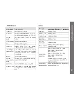
LED Indicator 

Radio mode 

LED indication 

Power on 

Red LED blinks 300ms 

Power low 

Orange  LED  blinks  50ms  every  2s, 
gives low power alarm every 15 mins. 

Standby 
mode 

Red  LED  blinks

every  5s  blinks 

50ms


Channel busy  Green LED always on 

Clone 

Orange LED always on 

In cloning 

Master 

radio 

red 

LED 

blinks, 

subsidiary radio green LED blinks. 

Low voltage 
and power off 

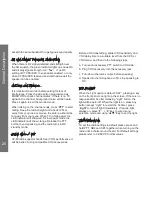
Low  voltage  alarms  every  second,  at 
the  same  time  orange  LED  blinks 
twice  per  second.  It  powers  off  after 
10 seconds 

Monitor 

Green LED always on 

Standby 
programming 
mode 

Reading: red LED blinks fast; Writing : 
green LED blinks fast 

Scan mode 

Green LED blinks once every 0.6s 

Sending voice  Low  power  TX:  orange  LED  always 

on;  High  power  TX:  red  LED  always 
on. 

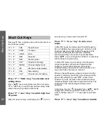
Tones 

Tone type 

Parameter

frequency _ duration


Key tone 

900Hz_75ms 

Bad key tone 

600Hz_75ms 

Confirm tone 

1800Hz_150ms 

Function 
enable tone 

900ms_75ms   

Function 
disable tone 

1800Hz_75ms   

Power on tone 

600Hz_75ms; 900Hz_50ms; 
1200Hz_75ms 

Low voltage 
alarm tone 

Beep 1.8KHz_50ms, off_40ms, 
Beep again 1.8KHz_50ms; 
Pause 180ms; 
Beep 1.8KHz_50ms, off_40ms, 
Beep again 1.8KHz_50ms, 
Then stop. 
It alarms every 15 minutes, if low 
voltage at start up or end of TX, it 
alarms instantly. 

Low voltage 
power off alarm   

Low voltage alarm every second and 
power off after 10s. 


21

General Description

Summary of Contents for VZ-88

Page 1: ...Operating Manual ...

Page 2: ... Used Charger 13 Battery and Charger 14 Battery Life Time 14 Battery Charging with Radio 14 Battery Charging Only 15 Charger LED Indicators 15 Charging Time 15 Cleaning and Maintenance 15 General Description 16 Familiar with VZ 88 Radio 16 LCD Icons 17 Digit Keypad 18 Basic Operations 18 Power On Off 18 Volume Adjustment 18 Frequency Display Mode VFO 18 Channel Save 18 Channel Display Mode MR 19 FM...

Page 3: ...equency offset 29 STEP VFO frequency step 29 CPS 29 Channel Information setting 29 VFO Information setting 29 Function parameter setting 30 DTMF setting 30 FM function setting 30 Scan List 30 Programmable side button 30 Monitor 30 Scan On Off 30 Nuisance Delete 30 High Low Power 30 Talk around Repeater 31 Back Light On Off 31 Clone Function 31 The Steps of Clone Operation 31 PL DPL Frequency Code Tab...

Page 4: ...their exposure and can exercise control over their exposure to meet the occupational limits in FCC and International standards This radio device is NOT authorized for general population consumer use This two way radio uses electromagnetic energy in the radio frequency RF spectrum to provide communications between two or more users over a distance It uses radio frequency RF energy or radio waves to...

Page 5: ... two way radio has a RF Exposure Product Label Also your Vertex Standard user manual or separate safety booklet includes information and operating instructions required to control your RF exposure and to satisfy compliance requirements Compliance with RF Exposure Standards Your Vertex Standard two way radio is designed and tested to comply with a number of national and International standards and ...

Page 6: ... procedures Guidelines Do not remove the RF Exposure Label from the device User awareness instructions should accompany device when transferred to other users Do not use this device if the operational requirements described herein are not met Operating Instructions Transmit no more than the rated duty factor of 50 of the time To transmit talk push the Push To Talk PTT button To receive calls relea...

Page 7: ... on board an aircraft Any use of a radio must be in accordance with applicable regulations per airline crew instructions Medical Devices Pacemakers The Advanced Medical Technology Association AdvaMed recommends that a minimum separation of 6 inches 15 centimeters be maintained between a handheld wireless radio and a pacemaker These recommendations are consistent with those of the U S Food and Drug...

Page 8: ...ilable Pull off the road and park before making or answering a call if driving conditions or regulations so require Operational Warnings For Vehicle with Air Bags Refer to vehicle manufacturer s manual prior to installation of electronic equipment to avoid interference with air bag wiring Do not place a portable radio in the area over an air bag or in the air bag deployment area Air bags inflate w...

Page 9: ...h as grain dust or metal powders Areas with potentially explosive atmospheres are often but not always posted Blasting Caps and Blasting Areas To avoid possible interference with blasting operations turn off your radio when you are near electrical blasting caps in a blasting area or in areas posted Turn off two way radio Obey all signs and instructions Operational Cautions Antennas Do not use any ...

Page 10: ...t operate a radio unit that has been approved as intrinsically safe product in a hazardous atmosphere if it has been physically damaged for example cracked housing An explosion or fire may result Do not replace or charge batteries in a hazardous atmosphere Contact sparking may occur while installing or removing batteries and cause an explosion or fire Warnings for Radios Approved as Intrinsically ...

Page 11: ...certified as intrinsically safe by the approving agency FM UL CSA CENELEC is tested as a complete system which consists of the listed agency approved portable approved battery and approved accessories or options or both This approved portable and battery combination must be strictly observed There must be no substitution of items even if the substitute has been previously approved with a different...

Page 12: ...p and plug the bottom lugs into radio rail slot c Press battery upper area until a Click sound is heard Detach Battery a Turn off radio b Press down the latch until battery is removed from radio c Remove the battery from the radio 11 Accessories Installtion Battery latch Rail slot Battery latch ...

Page 13: ...Antenna Installation a Screw antenna clockwise to top of radio as indicated above Detach Antenna a Screw antenna in an anti clockwise direction and remove from the radio 12 Accessories Installtion ...

Page 14: ... on the back of the battery b From the front side of the battery fix the belt clip with 2 screws c Connect the battery to the radio Power Adaptor and Commonly Used Charger a The radio comes with a commonly used charger and a power adaptor 13 Accessories Installtion ...

Page 15: ...ed the battery may be damaged and there may be overheating of the battery Battery Life Time If the battery has been fully charged then the power save function default setting can extend the battery life to 12 hours Note the calculation of battery using time is based on 5 TX 5 RX 90 standby standard duty factor Battery Charging with Radio a Place the charger on a flat surface b Plug the power adapt...

Page 16: ...reen when fully charged Charging Time It will take about 4 hours to charge the battery Cleaning and Maintenance Use wet and soft cloth to clean the radio surface Do not use alcohol or cleaning fluid If radio is not in use please ensure the earphone jack cover is in place Do not dip the radio in to water If radio is dropped into water please turn it off and take out the battery Use a soft cloth to ...

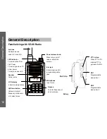
Page 17: ...voice Keypad To enter frequency or short cut menu Speaker Output voice Up Down button Up down to select frequency or channels or to select menu LCD display indicate working status Antenna Rubber antenna used to TX and RX Ear jack External ear jack Or programming cable jack PTT button Press PTT to TX release PTT to get ready for RX SB1 Programmable side button 1 SB 2 Programmable side button 2 Batt...

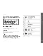
Page 18: ...ength indicator If the signal strength is strong the icon shows antenna and 6 bars If the signal strength is medium the icon shows antenna and 3 bars If the signal strength is week the icon shows antenna only Other icon descriptions Icon Function description 1 battery indicator 4 bars 2 Auto power off 3 Scan 4 VOX 5 Key tone 6 High power TX 7 Repeater 8 Monitor when FM enabled 9 CTCSS PL 10 CDCSS ...

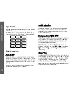
Page 19: ...b clockwise To decrease volume level turn the rotary knob counterclockwise Frequency Display Mode VFO In VFO mode the RX frequency is displayed which can be increased or decreased by pressing key per frequency step setting or it can be directly set by entering the frequency numbers All VFO settings can be modified through menu or short cut and icons such as high power scan add repeater indicate re...

Page 20: ...mber to save to then press V M key to confirm the settings Press PTT to exit this status A maximum of 25 FM channels can be set FM Channel Display Mode MR Press V M key to switch the FM VFO MR mode In MR mode the LCD left bottom displays the FM channel number 01 to 25 Use key to change FM channel or enter wanted channel number from keypad directly Short Cut Key Press the F key when blinks then pre...

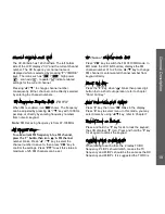
Page 21: ...ing and the radio turns to RX standby mode Hands Free VOX VZ 88 radio supports hands free VOX performance It will be better if using compatible VOX accessories Before VOX transmitting adjust VOX sensitivity and VOX delay time to a suitable level from the CPS or VOX menu and then do the following steps a Turn audio accessory PTT switch to VOX side b Plug VOX accessory into the accessory jack c Turn...

Page 22: ... LED blinks fast Writing green LED blinks fast Scan mode Green LED blinks once every 0 6s Sending voice Low power TX orange LED always on High power TX red LED always on Tones Tone type Parameter frequency _ duration Key tone 900Hz_75ms Bad key tone 600Hz_75ms Confirm tone 1800Hz_150ms Function enable tone 900ms_75ms Function disable tone 1800Hz_75ms Power on tone 600Hz_75ms 900Hz_50ms 1200Hz_75ms...

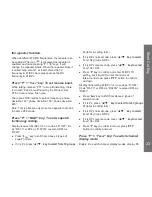
Page 23: ...In FM channel mode saved FM channel frequency will be scanned If FM signal was detected it will stop scanning and stay in the active channel and listen Press key to change scan direction or pressany other buttons to quit scanning In radio VFO mode the unit scans in the frequency range it supported with selected frequency step changing In radio channel mode the scan list channels will be scanned Wh...

Page 24: ...L as R 023N reversed DPL as R023I Press 6SQT key to shift from above 4 types of squelch mode If it is PL press key to select from 50 groups PL refer to coding form If it is DPL normal code press key to select from 104 groups N DPL If it is DPL reverse code press key to select from 104 I DPL Press F key to confirm and enter PL DPL TX setting but it ll quit if current channel is at talk around mode ...

Page 25: ...EL key To enter menu setting mode Press key to select menu then press F key to set or press other button key to cancel setting Press F 0LIST key To enter add scan channel setting mode Current channel will be added to scan list or deleted by operating it each time When the current channel is on scan list displays icon 24 Short Cut Key ...

Page 26: ...adio band width 12 5K 25K 25K 8 DW Dual watch RX signal in FM radio mode ON OFF ON 9 LIGHT Light options OFF KEY CONT KEY 10 LOCK Key lock mode K S PTT KEY ALL ALL 11 OPNMSG Opening message To edit open message for 6 char VZ SER 12 PSWD W Password setting To create a 4 digit password N A 13 ROGER End call tone ON OFF OFF 14 TOT Time out timer OFF 30 60 270s 180 15 TXSTOP ON OFF OFF 16 VOX voice co...

Page 27: ...splays 6 spaces If the channel alias is empty channel name is displayed as default CH nnn APO Auto Power Off APO is a background function it can monitor if the buttons were touched or valid RF signal is received If there is no response in 1 hour APO works 1 min before APO the APO icon will blink with a warning tone If RX squelch function is opened or changed or any other settings when APO is enabl...

Page 28: ... BEEP to ON OFF setting BW Band Width To choose the needed bandwidth you can select BW from the menu Press key to select 25K 12 5K Hz press F or PTT key to exit the setting mode press any other key to go back to idle mode DW Dual Watch When listening to the FM radio if a TX signal is received the FM radio will stop temporarily the icon FM blinks and the radio enters RX status After the signal has ...

Page 29: ...d protection when radio is up Note Please do not forget your password if forget please contact your local distributor ROGER Setting Select ROGER menu to ON OFF roger beep TOT TX Time out timer Setting Time out timer will protect the radio from damages caused by uncertain transmitting It can be set OFF 30s 60s 270s when it times out it gives a warning and stop transmission Enter TOT menu and press ...

Page 30: ...to transmit at repeater mode STEP VFO frequency step Frequency step has 5 selections 5 00KHz 6 25KHz 10 00KHz 12 50KHz and 25 00KHz In VFO mode user can press keys to increase decrease RX frequency with selected step CPS It s quite convenience to program following parameters or functions by connecting the radio to a PC with a compatible programming cable and run the VZ 88 CPS program Channel Infor...

Page 31: ...rt press as bellow functions None Monitor scan On Off Nuisance Delete High Low Power Talk around Repeater Back Light On Off Monitor When enabled the monitor button will give out squelch It is to check if current channel have been occupied and will temporarily get rid of the CTCSS DCS meanwhile it will receive some week signals Scan On Off Scan on Touch the programmed side button it starts from cur...

Page 32: ...ster light is on indicating the radio is ready for cloning b Connect the target radio to the master radio by cloning cable turn the target radio on c Press the PTT button of the master radio its red light blinks and meanwhile the target radio with green light blinks shows cloning after about 28s finish cloning the master radio resets and waits for next cloning request the target radio resets autom...

Page 33: ...0 0 23 141 3 33 177 3 43 210 7 4 74 4 14 103 5 24 146 2 34 179 9 44 218 1 5 77 0 15 107 2 25 151 4 35 183 5 45 225 7 6 79 7 16 110 9 26 156 7 36 186 2 46 229 1 7 82 5 17 114 8 27 159 8 37 189 9 47 233 6 8 85 4 18 118 8 28 162 2 38 192 8 48 241 8 9 88 5 19 123 0 29 165 5 39 196 6 49 250 3 10 91 5 20 127 3 30 167 9 40 199 5 50 254 1 32 PL DPL Frequency Code Table ...

Page 34: ...1 274 66 412 81 506 96 664 7 043 22 131 37 225 52 306 67 413 82 516 97 703 8 047 23 132 38 226 53 311 68 423 83 523 98 712 9 051 24 134 39 243 54 315 69 431 84 526 99 723 10 053 25 143 40 244 55 325 70 432 85 532 100 731 11 054 26 145 41 245 56 331 71 445 86 546 101 732 12 065 27 152 42 246 57 332 72 446 87 565 102 734 13 071 28 155 43 251 58 343 73 452 88 606 103 743 14 072 29 156 44 252 59 346 7...

Page 35: ...C Z U G 0 0 0 0 3 0 Copyright 2013 ...

Reviews: