background image

FCC ID:K6610342150 

IC: 511B-10342150 

Alignment


2/4


Vertex Standard Co., Ltd.
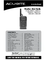


    50-

Ω


    RF Signal 

 Dummy load                                                                  Generator 
 
                                               RF Sampling 
 Inline Wattmater                      Coupler 
                                                                                      Transceiver 
 
 Deviation Meter                                    CT-71 
 
                                             CT-29 Connection 
  Frequeuncy                         Cable                               Power Supply 
    Counter                                                 IBM PC         13.8V DC 
                                             COM port 


Alignment Preparation & Precautions


A dummy load and inline wattmeter must be connected to the main antenna jack in all procedures that call 
for transmission, except where specified otherwise. Correct alignment is not possible with an antenna. 
After completing one step, read the following step to determine whether the same test equipment will be 
required. If not, remove the test equipment (except dummy load and wattmeter, if connected) before 
proceeding. 
Correct alignment requires that the ambient temperature be the same as that of the transceiver and test 
equipment, and that this temperature be held constant between 20 and 30 °C (68 and 86 °F). When the 
transceiver is brought into the shop from hot or cold air it should be allowed some time for thermal 
equalization with the environment before alignment. If possible, alignments should be made with oscillator 
shields and circuit boards firmly affixed in place. Also, the test equipment must be thoroughly warmed up 
before beginning. 
Before beginning, connect the transceiver and PC using the CT-71 programming cable as described in the 
EEPROM Programming chapter, and downloads the EEPROM data from the transceiver to the computer. 
Store this data in a disk file so that it can be saved and retrieved later. Using the table below, program the 
channel, CTCSS, and DCS alignment settings for your transceiver version. Upload this file to the 
transceiver. 
 

Note: Signal levels in dB referred to in this procedure are based on 0 dBm = 0.5 µV (closed circuit). 


Caution: Do not connect this line to ground, and be certain that the speaker has adequate capability 

to handle the audio output from the radio. 

Because of the bridge audio amplifier circuit used in the radio, it is necessary to construct and use a 

simple audio load test adapter as shown in the schematic diagram above, when conducting receiver 

alignment steps.


    3.5

φ

 PLUG 


                      Attenuated 

                                                                 Test Output (1/2) 
                                               2 

Ω

10 W 

 
                                                                  Ground 
 
                                               + 470 µF 
                                                2 

Ω

 10 W 


        AF Test Adapter Schematic 


Summary of Contents for VX-5500L

Page 1: ...lignment are not covered by the warranty policy Also VERTEX STANDARD must reserve the right to change circuits and alignment procedures in the interest of improved performance without notifying owners Under no circumstances should any alignment be attempted unless the normal function and operation of the transceiver are clearly understood the cause of the malfunction has been clearly pinpointed an...

Page 2: ...for thermal equalization with the environment before alignment If possible alignments should be made with oscillator shields and circuit boards firmly affixed in place Also the test equipment must be thoroughly warmed up before beginning Before beginning connect the transceiver and PC using the CT 71 programming cable as described in the EEPROM Programming chapter and downloads the EEPROM data fro...

Page 3: ...frequency channel CH4 then adjust T1005 on the Unit for 7V on the voltmeter Next select to the band low edge frequency channel CH1 and confirm about 3 1 V 2 8V 3 4V on the voltmeter Next select to the high band low edge frequency channel CH3 and confirm about 3 7 V 3 4V 4 0V on the voltmeter Key the transmitter and confirm about 7 V 6 9 V 7 1 V on the voltmeter Transmitter Output Power Select band...

Page 4: ... audio test adapter as described in the box below With the transceiver set to band center frequency channel and the RF signal generator tuned to the same frequency set the generator for 3 0 kHz deviation for 25 kHz steps with 1kHz tone modulation and set the output level for 1 µV at the antenna jack Adjust by control commands for tune from the computer for optimum SINAD reducing signal generator o...

Reviews: