


12
Important
In order to facilitate alignment over the complete switch-
ing range of the equipment it is recommended that the chan-
nel data in the transceiver is preset as the chart below.
Next select to the low edge frequency channel
and confirm above 1.00V to 1.80V on the volt-
meter.
Key the transmitter, and confirm above 1.10V to
2.00V on the voltmeter.
PLL Reference Frequency
With the wattmeter, dummy load and frequency counter
connected to the antenna jack, and select band center fre-
quency channel, key the transmitter and adjust
VR1001
on the RF-Unit, if necessary, so the counter frequency is
within 100 Hz of the channel center frequency for the trans-
ceiver version.
Alignment
The alignment mode is accessed by “Alignment mode”
command from the computer whilst switching on. And it
is operated by the alignment tool automatically.
During the alignment mode, normal operation is suspend-
ed. Use the alignment tool program running on PC.
PLL VCV
Connect the positive lead of the DC voltmeter to
the test point
TP1007
(VCV) on the RF-Unit, as
indicated in the figure, and the negative lead to
chassis ground.
Set the transceiver to the high band edge fre-
quency channel, then adjust coil
L1017
on the
Unit for 6.90V on the voltmeter.
Key the transmitter, and adjust coil
L1020
on the
Unit for 7.20V on the voltmeter.
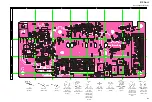
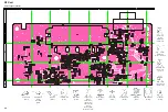
RF Unit Test & Alignment Points
TP1007
L1017
L1020
VR1001
C
HANNEL
CH 1
CH 2
CH 3
CH 4
CH 5
CH 6
CH 7
CH 8
C
HANNEL
S
PACE
Wide
Narrow
Wide
Narrow
Wide
Narrow
Wide
Wide
F
REQUENCY
(S
IMPLEX
)
154.100 MHz
154.100 MHz
154.100 MHz
154.100 MHz
154.100 MHz
154.100 MHz
134.100 MHz
173.900 MHz
T
ONE
F
REQUENCY
OR
, DCS
CODE
-
-
123.0 Hz (CTCSS)
123.0 Hz (CTCSS)
023 (DCS)
023 (DCS)
-
-
RF
P
OWER
High
Low
Low
Low
Low
Low
Low
Low
Summary of Contents for VX-2500EV
Page 5: ...5 Block Diagram 1 ...
Page 6: ...6 Block Diagram 2 ...
Page 7: ...7 Interconnection Diagram ...
Page 8: ...8 Note ...
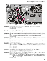
Page 18: ...18 RF Unit Jumper Information Note ...
Page 34: ...PANEL Unit 34 Note ...
Page 43: ...19 ...