


Parallel / Floppy Port
EPM-4 Reference Manual
Reference
–
31
Parallel / Floppy Port
P
ARALLEL
P
ORT
O
PERATION
The EPM-4 includes a standard bi-directional/EPP/ECP compatible LPT port which resides at the
PC standard address of 378h. The port can be enabled or disabled and interrupt assignments can
be made via the CMOS setup screen. The LPT mode is also set via the CMOS setup screen.
This connector uses IEC 61000-4-2-rated TVS components to help protect against ESD damage.
F
LOPPY
P
ORT
O
PERATION
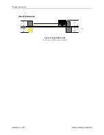
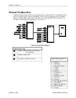
The parallel port can be used as a floppy disk interface. Select “FDD” as the LPT mode in CMOS
Setup and connect a floppy disk drive to the parallel port cable (CBL/CBR-2003) using the
floppy disk cable (CBL/CBR-2501). The diagram below shows how to connect the drive.
P
ARALLEL
/
F
LOPPY
P
ORT
P
INOUT
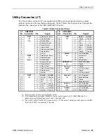
Table 6: LPT1 Parallel / Floppy Port Pinout
J2
Pin
Centronics
Signal
Floppy
Signal
Signal
Direction
1 Strobe
DS0*
Out
2 Auto
feed RPM
Out
3
Data bit 1
INDEX*
In/Out
4 Printer
error
HDSEL* In
5
Data bit 2
TRK0*
In/Out
6 Reset
FDIR
Out
7
Data bit 3
WP*
In/Out
8 Select
input
STEP* Out
9
Data bit 4
RDATA*
In/Out
10
Data bit 5
DSKCHG
In/Out
11
Data bit 6
N.C.
In/Out
12
Data bit 7
MTR0*
In/Out
13
Data bit 8
N.C.
In/Out
14 Ground
GND
—
15 Acknowledge
DS1*
In
16 Ground
GND
—
17 Port
Busy MTR1*
In
18 Ground
GND
—
19 Paper
End WDATA* In
20 Select
WGATE* In
EPM-4
Floppy
J2
VL-CBL/CBR-2003
VL-CBL/CBR-2501
DB-25 connectors
Summary of Contents for EPM-4
Page 2: ...EPM 4 AMD ÉlanSC520 processor module with 10 100 Ethernet and PC 104 Plus interface MEPM4 ...
Page 5: ......
Page 8: ...Table of Contents v Appendix B References 45 ...
Page 11: ...EPM 4 Block Diagram EPM 4 Reference Manual Introduction 3 EPM 4 Block Diagram ...
Page 14: ......
Page 24: ......
Page 50: ......


