background image

Cod. 1105033 - ß0

The  manufacturer  cannot  be  held  responsible  for  possible  inaccuracies  due  to 

printing or transcription errors in the present booklet.

The manufacturer reserves the right to make all modifications to its products deemed 

necessary for manufacture or commercial reasons at any moment and without prior 

notice, without jeopardising the essential functional and safety characteristics of the 

appliances.

Summary of Contents for VCLFSEE 365 Series

Page 1: ...ces Please ensure that this product is properly grounded The installer should leave these instructions with the consumer who should retain for local inspector s use and for future reference Electrical installation must be in accordance with the National Electrical Code ANSI NFPA70 latest edition and or local codes IN CANADA Electrical installation must be in accordance with the current CSA C22 1 C...

Page 2: ...pping the appliance the appliance must be secured by properly installed anti tip device packed with the appliance ALL RANGES CAN TIP INJURY TO PERSONS COULD RESULT INSTALL ANTI TIP DEVICE PACKED WITH RANGE SEE INSTALLATION INSTRUCTIONS ...

Page 3: ...ions and recommendations reported below are for your own safety and that of others They will also provide a means by which to make full use of the features offered by your appliance Please preserve this booklet carefully It may be useful in future either to yourself or to others in the event that doubts should arise relating to its operation This appliance must be used only for the task it has exp...

Page 4: ...e recycling symbol Do not attempt to modify the technical characteristics of the appliance as this may become dangerous to use Do not carry out cleaning or maintenance operations on the appliance without having previously disconnected it from the electric power supply After use ensure that the knobs are in OFF position Do not allow children or other incapable people to use the appliance without su...

Page 5: ... the appliance without your supervision The manufacturer cannot be held responsible for any damages caused by improper incorrect or unreasonable use of the appliance This figure is indicative only Hob rail Door handle s WARNING VERY IMPORTANT FIRE OVERHEATING HAZARD Do not place towels cloths etc onto the hob rail or oven door handle s whilst the product is in use or hot TO AVOID DAMAGE TO THE APP...

Page 6: ... 205 110 8 1 16 4 21 64 2100 700 W 4 Cooking zones residual heat indicators WARNING VERY IMPORTANT NOTICE Never obstruct the slots on the backguard 8 Backguard fitted 3 Backguard fitted features 1 Fig 1 1 Attention Disconnect the appliance from the mains if the ceramic hob is cracked and call the After Sales Service 2 1 2 1 3 4 ...

Page 7: ...ne 2 control knob 8 Front right cooking zone 1 control knob 9 Cooking zones power indicator light 10 Electronic programmer Please note This appliance incorporates a safety cooling fan which you will hear operating whenever the oven or grill are in use This fan may continue to run for several minutes after the appliance has been switched off This fan is to reduce the external temperature of the app...

Page 8: ...control and light up by selecting from the 12 positions on the control knob fig 2 1 The heat intensity can be regulated continuously from OFF to 12 max VERY IMPORTANT TO SWITCH ON ALWAYS LIGHTLY PRESS THE CONTROL KNOB THEN TURN IT Check that the hob is clean and then switch on by press and turning the control knob DOUBLE COOKING ZONE Incorporating 2 heating elements you can control and light up to...

Page 9: ...me approx 30 min after they have been switched off Scrupulously follow the cleaning instructions Do not drop heavy or sharp objects on the glass ceramic cooktop Never cook the food directly on the glass ceramic cooktop but in special pans or containers COOKING ZONES POWER INDICATOR LIGHT fig 2 6 When the ceramic hob is working the ON pilot light in the control panel will be on fig 2 6a COOKING ZON...

Page 10: ...g and cooking in the multifunction oven takes place as follows by normal convection The heat is produced by the upper and lower heating elements by forced convection The heat produced by the circular element is distributed throughout the oven by the fan by semi forced convection The heat produced by the upper and lower heating elements is distributed throughout the oven by the fan by radiation The...

Page 11: ...ng times vary according to the quantity and type of foods to be defrosted TRADITIONAL CONVECTION COOKING The upper and lower heating elements switch on The heat is diffused by natural convection and the temperature must be set between 120 F 50 C and 480 F 250 C via the thermostat knob Recommended for For foods which require the same cooking temperature both internally and externally i e roasts spa...

Page 12: ... The temperature can be set between 120 F 50 C and 480 F 250 C via the thermostat knob For correct use see the VENTILATED BROILING section Recommended for For grill cooking when a fast outside browning is necessary to keep the juices in i e veal steak steak hamburger etc CONVECTION COOKING WITH VENTILATION The upper and lower heating elements and the fan turn on The heat is dispersed by forced con...

Page 13: ...rmostat knob to position 260 F 130 C When sterilization has begun that is when the contents of the jars start to bubble turn off the oven and let cool VENTILATED BROILING Ventilated broiling may be done by selecting with the function selector knob the hot air completely envelops the food that is to be cooked Introduce the food to be cooked positioning the grill pan as close to the infra red elemen...

Page 14: ...od to be cooked above the broiling pan Introduce the broiling pan fig 3 6 in the oven The broiling pan should be placed above the shelf and it should be centered with the broil element fig 3 5 Do not broil without using the broiling pan Important Use always suitable protective gloves when inserting removing the broiling pan shelves pans or other cooking utensils from the oven Fig 3 6 WRONG CORRECT...

Page 15: ...ed cooking program To increase the numbers on the digital display To decrease the numbers on the digital display ELECTRONIC CLOCK fig 4 2 The programmer is equipped with an electronic clock with lighted numbers which indicate hours and minutes Upon immediate connection of the oven or after a blackout 12 00 will flash on the programmer panel To set the hour it is necessary to push the button and th...

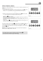
Page 16: ... cooking time by pressing the button the cooking time already added to the clock time will appear and the button fig 4 6 if you pass the desired time you may get back by pushing the button After this setting the symbol will go off If after this setting the AUTO flashes on the panel and a buzzer goes off it means there was an error in the programming In this case modify the end of cooking time or t...

Page 17: ...knobs see specific chapters The oven is switched on and it will be switched off automatically at the end of the desired time During cooking the symbol remains on and by pressing the button you can see the time that remains till the end of the cooking At the end of cooking the oven and the symbol will turn off the AUTO will flash and a buzzer will sound that can be stopped by pushing any of the but...

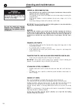
Page 18: ...e lemon juice tomato sauce vinegar etc can damage the enamel if left too long PAINTED PARTS AND SILK SCREEN PRINTED SURFACES Clean using an appropriate product Always dry thoroughly IMPORTANT these parts must be cleaned very carefully to avoid scratching and abrasion You are advised to use a soft cloth and neutral soap STAINLESS STEEL ELEMENTS Stainless steel parts must be rinsed with water and dr...

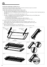
Page 19: ... surface Avoid using knives and pointed objects as they could damage the surface of the top Also avoid using abrasive sponges or wire wool which can permanently scratch the pyroceram surface ATTENTION MOST IMPORTANT If cleaning the glass ceramic hob using a special scraper tool take extra care to avoid damaging to the seal at the edges of the glass ceramic surface 5 OVEN ACCESSORIES INSTALLATION A...

Page 20: ...ted above the oven shelf shall run out towards the oven door do not use the top shelf position the short bend on the wire support shall face the inside of the oven the oven shelf must be fitted so that the guard rail faces the inside of the oven To remove the RH and LH sliding guides from the wire support Find the safety locks These are the tabs that clip over the fixing wire arrow 1 in fig 5 9 Pu...

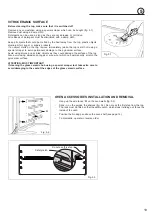
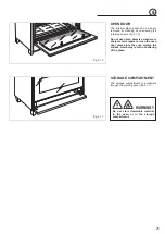
Page 21: ...easily removed for cleaning by unscrewing the retaining screws fig 5 10 Do not use harsh abrasive cleaners or sharp metal scrapers to clean the oven door glass since they can scratch the surface which may result in shattering of the glass WARNING Do not store flammable material in the oven or in the storage compartment Fig 5 10 Fig 5 11 5 ...

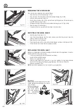
Page 22: ...tly close the door fig 5 12c until left and right hinge levers A are hooked to part B of the door fig 5 12b Withdraw the hinge hooks from their location following arrow C fig 5 12d Rest the door on a soft surface To replace the door repeat the above steps in reverse order REFITTING THE OVEN DOOR Hold the door firmly fig 5 12 Insert the hinge tongues into the slots making sure that the groove drops...

Page 23: ...accessories Do not place cooking utensils or plates directly onto the oven base Do not place hot enamel parts in water Leave them to cool first Do not allow vinegar coffee milk saltwater lemon or tomato juice to remain in contact with enamel parts i e inside the oven Do not use abrasive cleaners or powders that will scratch the surface of the stainless steel and the enamel Do not attempt to repair...

Page 24: ...transcription errors in the present booklet The manufacturer reserves the right to make all modifications to its products deemed necessary for manufacture or commercial reasons at any moment and without prior notice without jeopardising the essential functional and safety characteristics of the appliances ...

Reviews: