background image

10

WMC Series Woodburning Fireplace

20000583

Framing the Ceiling Hole

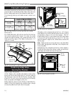
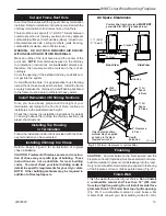
Frame the ceiling chimney hole as shown in Figure 13.  It is 

good practice to use framing lumber that is the same size 

as the ceiling joists; this is a requirement at attic level.
The  following  table  gives  firestop  spacer  model  num-

bers:

If fireplace is to be elevated above the floor, a “Z” shaped 

metal safety strip must be fabricated and used to protect 

combustible  surfaces  in  front  of  the  fireplace.   This  “Z” 

shaped safety strip is not provided but must be fabricated 

of  metal  with  each  horizontal  leg  at  least  1

Z\x

"  (38  mm) 

wide and equal in length to the metal strips provided with 

the fireplace.

Note:  

Safety strips are not required over noncombustible 

floors where all supports at the base of the fireplace are 

noncombustible.
Nailing flanges are integrated on the face of the fireplace. 

To level the box and secure it firmly in place, bend the nail-

ing flanges and install as shown in Figure 15.

Fig. 13 

 Typical frame for ceiling chimney hole.

FP551

WF551

BR/BC

9/29/97

See 
Fig. 12

See 
Fig. 12

Existing 

Ceiling 

Joists

Ceiling

New Framing 

Members

Chimney 

Hole

Fig. 12

 Ceiling chimney hole sizes necessary for installing 

firestop spacer.

  Size of Chimney 

Vertical 

30°


8" Flue 

SKFS2A 

SKFS6A


"SK" Series 

14

Z\x

" x 14

Z\x

14

Z\x

" x 25

Z\x

"


(368mm x 368mm)  (368mm x 648mm)


8" Flue 

FS2A 

FS6A

  "S" Series 3-Wall 

17

Z\x

" x 17

Z\x

17

⁷\,

" x 29

B\,

"


(445mm x 445mm)  (454mm x 753mm)


Angle of Chimney at Ceiling

The inside dimension of the frame must be the same as 

the hole size selected from Figure 13 in order to provide 

required air space between the outside diameter of the 

chimney and the edges of the framed ceiling hole. (1

Z\x

- SK8; 2" - 3 wall)

 Positioning, Safety Strips, 

Securing The Fireplace

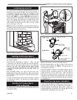
Slide fireplace into position.
Lift the fireplace front slightly and slide the metal safety 

strips under front bottom edge about 1

Z\x

" (38 mm), allowing 

the remainder to extend in front of firebox. Overlap strips 

at least 1/2" (13 mm) to provide a positive joint. (Flat safety 

strips are packed with fireplace.) (Fig. 14)
Safety strips are used to ensure that any combustible ma-

terials in front of the fireplace are protected even though 

a noncombustible hearth extension is required.

FPC557

Fig. 14

  Safety strip installation.

FPC557

WMC Safety strip installation

circulatin models

1/29/99   djt

Metal Safety 

Strips

(1, 2 or 3 Pieces)

Z\x

" (13mm)

Min. Overlap

1Z\x

"

(38mm)

"Z" 

Safety 

Strip

Fire-

Place

Plat-

Form

Hearth Ext.

(not supplied)

FPC549

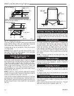
Fig. 15 

 Fasten fireplace in position.

FPC549

Nail flange/standoff

circulating models

1/29/99   djt

Nail Top 

Standoffs

Nail Side-

Nailing 

Flanges

Summary of Contents for Royal Collection WMC36

Page 1: ...se in U S Canada Underwriter s Laboratories Report No MH7603 DO NOT DISCARD THIS MANUAL Retain for future use 20000583 1 13 Rev 31 FP583A WMC 12 18 98 WMC Series Woodburning Fireplaces Homeowner s Installation and Operating Manual ...

Page 2: ...t part not manufactured or approved by Vermont Cast ings Group in combination or assembly with a Vermont Castings Group fireplace system not withstanding any independent testing laboratory or other third party approval of such component parts or accessory Any such action may possibly cause a fire hazard Consult local building codes to ensure that you are in compliance before installing the firepla...

Page 3: ...ia 203mm 3 6 9 1 4 m m Fig 2 WMC42 Series specifications and framing FP592A WMC42 Series Woodburning Fireplace Circulating Model FP590A WMC36 SPECS 1 28 99 djt B 1 6 m m Z x 13mm Z x 36 914mm 35Z v 895mm 40 1016mm B 16mm 19C v 502mm 1C v 45mm 35Z x 902mm 21 7C v 197mm 7Z x 191mm Recessed Nailing Flange 11 Dia 279mm Rough Opening Width 41 Rough Opening Height Rough Opening Depth Gas Line Access 47 ...

Page 4: ...d Outlet Grille Damper Control Gas Line Knockout both sides Screen Grate Firebox Metal Safety Strips 1 2 or 3 pieces Inlet Grille Outside Air Cover Plate Electrical Access Gas Line Access both sides Nailing Flange Standoff Batt Insulation cut out around firestop Firestop Ceiling Level A B C FP1531 hearth dimensions 9 04 djt Front Width Back Width Depth A B C WMC36 33Z x 20Z v 18Z v 851 mm 514 mm 4...

Page 5: ... 1 0 0 1 0 31 60 0 1 0 1 0 34 65 0 0 2 0 0 37 70 1 1 0 1 1 41 77 0 0 1 1 1 45 83 0 1 2 0 1 47 87 0 0 0 2 1 51 94 0 1 1 1 1 53 98 0 0 3 0 1 56 103 0 1 0 2 1 59 108 0 0 2 1 1 62 113 0 1 3 0 1 64 117 0 0 1 2 1 68 124 0 1 2 1 1 70 128 0 0 0 3 1 74 134 0 1 1 2 2 78 140 0 0 3 1 2 81 146 0 1 0 3 2 84 151 0 0 2 2 2 87 156 0 1 3 1 2 89 160 0 0 1 3 2 93 166 0 1 2 2 2 95 170 0 0 0 4 2 99 177 0 1 1 3 2 101 18...

Page 6: ...t 2 609 mm above the peak of the roof but never less than 3 914 mm in height above the highest point where it passes through the roof 2 If a horizontal distance from the chimney to the peak of the roof is more than 10 3 m a chimney height refer ence point is established that is on the surface of the roof a distance of 10 3 m from the chimney in a horizontal plane The top of the chimney must be at ...

Page 7: ...mates If you live in a cold climate it is not required but highly recommended that you insulate fireplace enclosure to eliminate cold air penetration as much as possible Insulate base of fireplace with a noncombustible insula tion rated for a minimum of 300 F Insulating is very important for outside wall installations over a concrete slab If fireplace is installed on a platform insulation should b...

Page 8: ...uctions Read all instructions before beginning installation Follow instruc tions carefully The SCVS speed control may be used as an alternate wall switch in lieu of the single pole Listed 1 5 Amp 120V switch described in the fan or fireplace installation instruc tions Installation Instructions For mounting the speed control a 2 deep standard electri cal box should be used Using wire nuts supplied ...

Page 9: ...t Castings Group elbows Use the 30 Offset Elbow table on Page 5 to determine proper offset and parts required Each offset requires two 2 elbows The second elbow is equipped with support straps It is very important to install the second elbow in each offset as close to the ceiling or support as possible so the elbow straps can be secured to framing members to help support the weight of the chimney ...

Page 10: ...installing firestop spacer Size of Chimney Vertical 30 8 Flue SKFS2A SKFS6A SK Series 14 x 14 14 x 25 368mm x 368mm 368mm x 648mm 8 Flue FS2A FS6A S Series 3 Wall 17 x 17 17 x 29 445mm x 445mm 454mm x 753mm Angle of Chimney at Ceiling The inside dimension of the frame must be the same as the hole size selected from Figure 13 in order to provide required air space between the outside diameter of th...

Page 11: ... collar on top of the fireplace Install the pipe as pictured in Figure 17 When you get a good lock you will hear the pipe clearly snap together Once sections are snap locked in place it is extremely difficult to get them apart Make sure the pipe is firmly snapped and locked together as each pipe section is mounted When installing elbows only outer pipe will snap lock Middle pipes simply slide into...

Page 12: ...ld with the flanges on its base extending down into the framing hole Nail each corner of attic insulation shield to the framing members of the ceil ing hole using 8d nails Attic shields are not required at the roof Continue Installing Pipe to Complete Run Continue attaching pipe sections to complete system to next level always being careful that the pipe is firmly snapped locked in place before pr...

Page 13: ...ing Top Housing or Termination Follow the installation instructions provided with the chim ney termination you have selected Installing Chimney In a Chase Refer to Page 4 Figure 3 for an illustration of a typical chase installation CAUTION Treatment of firestop spacers and construc tion of chase may vary with type of building These instructions are not a substitute for local building codes You mus...

Page 14: ...otected with a specifically built wall shield as described below The special wall shield design described in Figure 19 is an alternate method of adding protection to side walls Rt must 1 85 minimum FP531b Fig 22 Mantel clearance FP531b mantel clearances 9 03 djt Z x 12 305mm Max 12 305mm Min 1Z x 38mm 6 159mm Min Combustible Mantel and Trim Finished Wall Header Standoff Noncombustible Material Gri...

Page 15: ...d from manufacturer of the material Factors are related by the formula K 1 R T given thickness R thermal resistance for a given thickness T K thermal conductivity Noncombustible material with a lower R value may be used provided thickness of material is sufficiently greater to maintain an equivalent total thermal resistance Rt Minimum Wall Clearances WITH Noncombustible Surround Facing WITHOUT Non...

Page 16: ...doffs Safety Strips Must be overlapped Z x minimum Hearth Extension Insulation Side View FP550 Fig 26 Sealing gaps How to Operate Your Fireplace Your fireplace can provide countless hours of pleasure and security However use your fireplace carefully because any time you build a fire inside a house a problem may develop Open Flue Damper The flue damper is meant to be closed only when the fire is co...

Page 17: ...to totally seal between the pipe and tube Note Gas pipe should not come in contact with any wood structures until it has reached a point at least one 1 inch away from fireplace side NOTE When installing an ANSI Z21 11 2 ventless appli ance the finishing materials used for the mantel must be rated at 250 F or greater BTU input of a gas appliance installed in fireplace should be rated less than 100 ...

Page 18: ...replace 26D0131 26D0131 5 Damper Knob Wood 7536177 7536177 6 Firebrick Left Side 3041104 3034102 7 Firebrick Back 3030102 3034104 8 Firebrick Right Side 3041105 3034103 9 Firebrick Hearth 3041103 3034105 10 Screen Rod two per fireplace 26D0138 61D0500 11 Top Brick Retainers three per fireplace 3030172 3030172 12 Cable Clips four per fireplace 7512135 7512135 13 O S A Assy 20003076 20003076 14a Doo...

Page 19: ...se an unapproved component to make any modifications you may create a possible fire hazard and will void the Vermont Castings Group warranty In ad dition such action may void the coverage provided by the owner s insurance Accessories Contact your Vermont Castings Group distributor or dealer for finishing Mantels available in a wide selection of styles Glass Door Optional Bi Fold door set Pewter fi...

Page 20: ...le chimney cap used to PLTSK8 SK8 terminate chimney through a chase Includes adapter Flashing not included Chase Top Housing Square chimney cap used to terminate chimney SLTSK8 SK8 through a chase Includes adapter Flashing not included SK8 Chimney Sections Pipe used to build 8 SK8 flue systems SK81 1 Long SK818 1 Long SK83 3 Long SK84 4 Long SK8 Chimney Elbows Elbow used to create an offset in an ...

Page 21: ...rom the chimney to combustible framing With 16 center lines Attic Insulation Shield Used to prevent attic insulation from FS2100 HT 3 wall CF 11 contacting the chimney system Canada Chimney Collar Enclosure Installs on the over the chimney collar of the CCE SK SK8 fireplace provides outside air to assist in cooling the chimney system Attic Insulation Shield Used to prevent insulation from coming i...

Page 22: ...22 WMC Series Woodburning Fireplace 20000583 ...

Page 23: ...ure dif ferentials produced by wind Broken glass components Cracks in ceramic and castable parts that do not affect safe operation We do not warrant this fireplace to be in compliance with your local building code Building codes vary greatly throughout the country and you should determine whether your local building code contains restrictions on the use of this fireplace before you purchase it Blo...

Page 24: ...Vermont Castings Group 149 Cleveland Drive Paris Kentucky 40361 www vermontcastingsgroup com ...

Reviews: