MX 900 Series Installation Guide
21
May 13, 2015
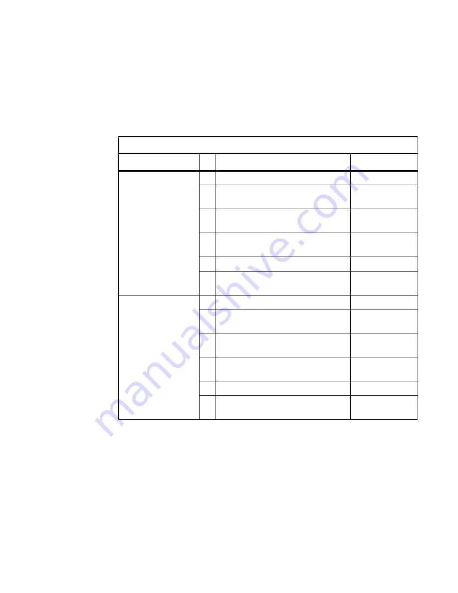
I/O Modules
The MX 900 Series
terminals use one of six I/O Modules to make the following
connections. See the following section for I/O Module Illustrations.
Note:
Use the Ethernet port on the I/O module only if the multiport cable is
not attached. Otherwise, use the Ethernet port on the multiport cable.
I/O Modules
Terminal
#
Description
I/O Module P/N
MX 915
P/N M132-409-01-R
1
AUD, BERG ONLY, NO TAILGATE
132-601-00-R
2
PWR, AUD, BERG W/ TAILGATE,
ETH, USB OTG, COM 2
132-602-00-R
3
PWR, AUD, POE, USB OTG, USB
HOST, COM 1, COM 2
132-603-00-R
4
PWR, AUD, ETH, USB OTG, COM 1,
WIFI/BT
132-604-00-R
5
AUD, BERG W/ TAILGATE
132-605-00-R
6
PWR, ETH, USB HOST, USB DEVICE,
COM 2
132-606-00-R
MX 925
P/N M132-509-11-R
P/N M132-509-01-R
P/N M132-509-21-R
1
AUD, BERG ONLY, NO TAILGATE
132-601-00-R
2
PWR, AUD, BERG W/ TAILGATE,
ETH, USB OTG, COM 2
132-602-00-R
3
PWR, AUD, POE, USB OTG, USB
HOST, COM 1, COM 2
132-603-00-R
4
PWR, AUD, ETH, USB OTG, COM 1,
WIFI/BT
132-604-00-R
5
AUD, BERG W/ TAILGATE
132-605-00-R
6
PWR, ETH, USB HOST, USB DEVICE,
COM 2
132-606-00-R
Summary of Contents for MX 915
Page 1: ...MX 900 Series Installation Guide Date May 13 2015...
Page 2: ......
Page 4: ......
Page 8: ...2 MX 900 Series Installation Guide May 13 2015...
Page 38: ...32 MX 900 Series Installation Guide May 13 2015...
Page 40: ...34 MX 900 Series Installation Guide May 13 2015...
Page 44: ...38 MX 900 Series Installation Guide May 13 2015...