24
-
Front and back face clearance; adjustable by shim
Rotor thickness and body depth are fixed at manufacturer. Therefore, with the correct rotor size
selected, the only maintenance adjustment that can be made is the proportion of front and rear
clearance. Measure the front clearance as follows:
1.
The rotor to rotor housing back face clearance is maintained by the shim(s) (45).
2.
Check that the rotor case is tight to the gearbox (1A). And check the rotor bolts (35) are
tight.
3.
Measure the clearance between the back face of the rotor case and the back of the rotor
with a feeler gauge with reference of the above recommended back face clearance.
4.
If incorrect, adjust by adding or removing shim(s) (45) from behind the rotor case.
5.
Check each rotor and adjust as necessary.
6.6 ROTOR TIMING
Rotor timing is critical for the pump operation and must be precisely maintained to provide
maximum pumping efficiency, and to prevent contact between rotors during operation. If pumping
efficiency is below expectations, or if rotors contact during operation (within rated differential
pressure), check rotor timing and adjust if incorrect. Also check rotor timing after any gearbox
dismantling when the gears are removed and/or replaced.
Check Rotor timing as follows:
1. Assemble each rotor in its normal location on the drive shaft and the idle shaft. Assemble
each rotor bolt and tighten hand tight.
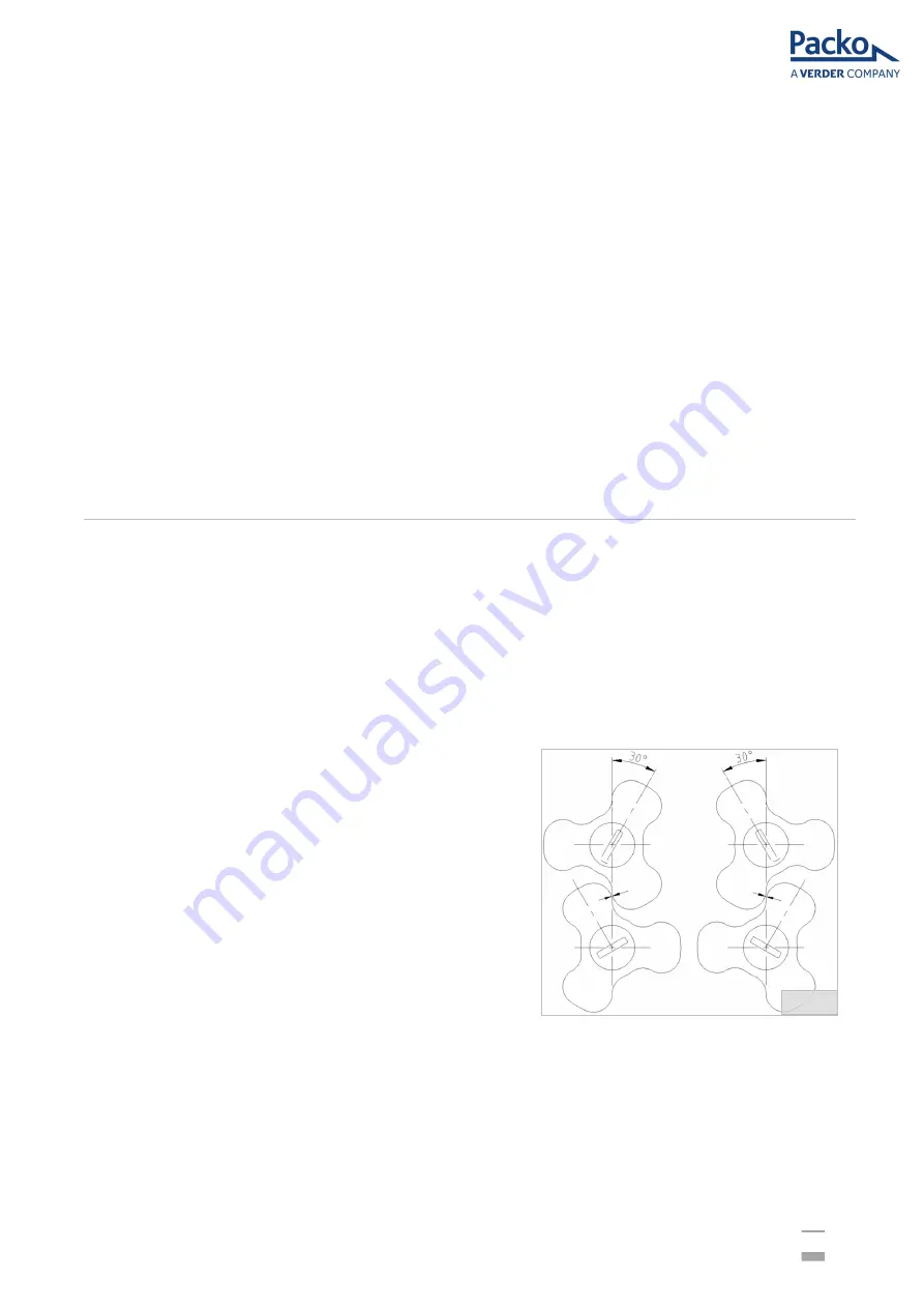
2. Rotate the shafts 30 degrees and measure gap
as illustrated by arrows in Figure 27. Rotate the
shafts 60 degrees to the opposite direction and
measure the gap as illustrated.
3. The Rotors are correctly timed when the gap
measured at both locations are equal. If the
gap is unequal, adjust the timing as follows.
4. Rotor timing is determined by the relative
location of the two helical gears (14) on the
shafts. Gear spacers (17) are used to adjust
the location and the timing. When adjusting
timing, move only one of the two gears.
Fig. 27


