background image

3.0   3216 Controller

If not all the segments are used for a program, the Ramp & Dwell of each of the
subsequent segments should be set to OFF.

A program will end in one of two ways, either revert to the control setpoint or dwell at
the temperature set in the last segment used. When a program finishes on a dwell and
the dwell time expires the temperature will revert to the control setpoint.

Note: Before operating a program ensure that the control setpoint is set to Zero to
avoid unexpected heating at the end of the program.

3.7.9

Running a Program

If using the 3216P5 controller press scroll

to display PROG <PROGRAM NUMBER>.

Select the required Program Number before operating a Program.

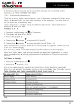
Table below shows the key presses to operate a program.

Operation

Action

Indication

To RUN a program

Press and quickly release
+

Indicator – RUN = ON
Scrolling Display – Current
Program state

To HOLD a program

Press and quickly release
+

Indicator – RUN = Flashing

Scrolling Display – Program Hold

To RESET a program Press and hold

+

for

more than 1 second

Indicator – RUN = OFF

Scrolling Display - None

Program Ended

Indicator – RUN = OFF

Scrolling Text – Program End

To RESET a
program after it has
completed

Press and hold

+

for

more than 1 second or press

and quickly release Ack

Indicator – RUN = OFF

Scrolling Display - None

3.7.10

Program Status

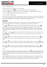
While the program is operating in level 1 or level 2, the home display shows two values
at any one time:

3.7.11

Process Value

The upper display shows the current temperature of the product.

3.7.12

PSP, Segment Type and Number

The lower display continually alternates between the programs current set value
(Program SP = PSP) and scrolling text, indicating the current status of the program
whether RAMP or DWELLING followed by the segment number.

Additional information can be obtained using the scroll

key while the program is

operating.

26

Summary of Contents for CARBOLITE GERO 3216 Series

Page 1: ...Installation Operation and Maintenance Instructions 1200 C E Range Tube Furnace EVA Model 300mm 3216 Controller EVA 12 300B 3216 Controller MEN EVA12300B 004_3216 09 07 2019 ...

Page 2: ...onto the vertical stand 11 2 3 4 Figure Tube furnace positioned horizontally on the stand 12 2 3 5 Figure Exploded view showing how to fit the work tube in the EVA 13 2 3 6 Figure Tube support 14 2 3 7 Figure Tube support assembly 14 2 3 8 Figure Tube support and end seal assembly 15 2 3 9 Figure Tube support and end seal assembly 15 2 3 10 Figure View showing how to support the work tube in a ver...

Page 3: ...9 Running a Program 26 3 7 10 Program Status 26 3 7 11 Process Value 26 3 7 12 PSP Segment Type and Number 26 3 8 Controller Options 29 3 8 1 Digital Communications RS232 29 3 8 2 Digital Communications RS485 29 3 8 3 Comms Address 29 3 8 4 Alarm Option 30 3 9 Temperature Controller Replacement 30 3 10 3216 Controller Navigation Diagram 30 4 0 2132 Over Temperature Controller Description if fitted...

Page 4: ... Spare Parts and Spare Parts Kit 41 7 0 Repairs and Replacements 42 7 1 Safety Warning Disconnection from Power Supply 42 7 2 Safety Warning Refractory Fibre Insulation 42 7 3 Temperature Controller Replacement 42 7 4 Solid state Relay Replacement 43 7 5 Thermocouple Replacement 43 7 6 Element Replacement 43 7 7 Fuse Replacement 44 8 0 Fault Analysis 45 A Furnace Does Not Heat Up 45 B Product Over...

Page 5: ...11 0 Specifications 52 11 1 Environment 52 Furnace drying out process 53 5 ...

Page 6: ...d to the elements Heat switch the switch disconnects power to the heating elements unless this switch is OFF there is a danger of electric shock when inserting objects into the product 1 2 General Warnings DANGER Electric shock Read any warning printed next to this symbol WARNING Risk of fatal injury DANGER Hot surface Read any warning printed next to this symbol WARNING All surfaces of a product ...

Page 7: ...work tube adaptors or it could be possible for an operator to access electrically live element coils that could cause serious injury or death 8 Warning label Switch off the furnace before loading and unloading The furnace heaters must be switched OFF using the heater switch item 2 in figure 1 3 1 when the furnace is being loaded or unloaded The work tube can become electrically conductive at high ...

Page 8: ...er ON and OFF to the furnace heating ele ments 3 Heater ON light indicates that the furnace heating elements are energized 4 Product rating label indicating the product serial number and electrical inform ation 5 Access holes to front panel fixing screws 6 Warning label Disconnect the mains supply before removing this cover 7 Warning label Do not operate without a work tube 8 Warning label Switch ...

Page 9: ...al spillage or hot materials The surface on which the equipment is mounted should be stable and not subject to movement or vibrations The height of the mounting surface is important to avoid operator strain when loading and unloading samples Unless otherwise stated elsewhere in this manual ensure that there is at least 150 mm of free space around the back and sides of the product Clear space is re...

Page 10: ...bling the stand and mounting the furnace Tools required 4 mm Allen key The assembly of the vertical stand is as follows with reference to 2 3 1 2 3 2 and 2 3 3 Place the vertical stand base item 1 on the floor or bench on which it is to be assembled l Position the vertical stand upright 2 on the stand base in line with the fixing holder l Secure the stand upright to the base using the 6 x M6 dome ...

Page 11: ...mbling the stand Index to numbered items in Figure 2 3 2 and Figure 2 3 3 1 Vertical stand base 2 Vertical stand upright 3 Fixing screws M6 x 16 dome cap screw 4 Washer M6 5 Tube furnace 6 M6 screw knob 2 3 3 Figure Mounting the fur nace onto the vertical stand 11 2 0 Installation ...

Page 12: ...o 2 3 5 Note that standard length work tubes are also referred to as tubes suitable for working in air they are 150 mm longer than the heated length of the furnace see the table in section 11 0 Read section 7 2 before fitting the work tube l Remove the top work tube end guard item 8 hen remove the work tube adaptor fix ing bracket 4 that holds the work tube end stop 7 and the work tube adaptor 3 i...

Page 13: ... without an end seal care should be taken not to over tighten on to a bare tube especially if the tube is either quartz or thin wall section l Before the extended work tube can be fitted the work tube end stops for the stand ard length work tube must be removed from both ends of the furnace This is done by removing the furnace end guard 8 and the work tube adaptor brackets 4 to release the work tu...

Page 14: ... 0 Installation l Figure 2 2 shows an exploded view of all the required parts l Figure 2 2 shows the assembled parts as they would be used 2 3 6 Figure Tube support 2 3 7 Figure Tube support assembly 14 ...

Page 15: ... Figure Tube support and end seal assembly 2 3 9 Figure Tube support and end seal assembly For extra stability of the tube repeat the assembly instructions above as shown in figure 2 3 10 15 2 0 Installation ...

Page 16: ...et order option or installation in customer s test rig mounting frame It is the customer s responsibility to carry out a risk assessment on the siting and mounting of the furnace and to ensure that it is operated in a safe manner see section 2 2 for the recommended siting instructions The fitting of the work tube is covered in the previous section 2 4 1 Figure Tube furnace shown without a stand fo...

Page 17: ...s vacuum end seal is fitted either horizontally or vertically the insulation plug hooks onto the end seal hook see figure B Alignment of radiation shields is similar to that of insulation plugs see figure C If a metal work tube is being used in the furnace ensure that it is earthed See the safety warning in section 5 4 Figure A Cross section view showing standard length work tube insulation plug f...

Page 18: ...al supply should be fused at the next standard size equal to or higher than the design current Where a supply cable is supplied there are internal supply fuses in which case customer fusing is preferred but not essential See section 10 0 for furnace rating power current and fusing information The external connection should be either a permanent connection to a fused isolator supply or to a socket ...

Page 19: ...gle program of 8 ramp dwell segments The 3216P1 can also be used as a simple temperature controller 3 3 3216P5 The 3216P5 is a digital temperature controller which uses PID algorithms to give excellent temperature control This controller can store up to 5 programs of 8 ramp dwell segments The 3216P5 can also be used as a simple temperature controller 3 4 Operation 3 4 1 Controller Layout Key A Pow...

Page 20: ...ired temperature Setpoint 3 5 2 Changing the Setpoint Press Up or Down to select the required SP If the SP is higher than the measured temperature the OP1 indicator will illuminate in the top left corner of the display indicating that the controller is calling for power giving an output The controller will immediately attempt to reach the setpoint and then maintain it This will cause the product t...

Page 21: ...red PASS should momentarily be displayed and then revert to the level 2 home display If an incorrect code is entered the display reverts back to Level 1 home display When level 2 operations have been completed the supervisor must return to Level 1 either manually or by switching the instrument off and back on There is no time out function To Return to Level 1 1 Press and hold the page Key 2 Press ...

Page 22: ... power setting OP Hi may be accessible or locked For silicon carbide heated furnaces the parameter is accessible to allow compensation for element ageing In many models the maximum output power setting depends on the supply voltage see section 10 0 3 6 2 Customer ID A furnace or oven identification number can be entered if required This maybe used to identify one of many units for production or qu...

Page 23: ...ect pass code is entered When the correct pass code is entered and PNT LO Adjust Low Point is displayed Use the up and down keys to enter the Low Temperature Point which you want to apply an Offset Press scroll until the display shows OFS LO Adjust Low OFFset Use the up and down keys to enter the amount Offset you want to apply to the Low Temperature Point Press scroll until the display shows PNT ...

Page 24: ... product temperature reaches 590 C the program will then continue to control again The holdback will only apply once per segment therefore when control has been re established the holdback will not apply again to that segment even if the product temperature goes outside the holdback band Holdback can only be accessed in supervisor level level 2 by scrolling with the scroll until the display shows ...

Page 25: ...splay shows H BACK Program Holdback If a holdback value is required use the up down to enter the required value or select OFF if no holdback is required 3 7 6 Ramp Rate Press scroll until the display shows RMP 1 Ramp Rate 1 Using the up down enter the value for the first ramp rate depending on the Ramp Units selected If the Ramp segment is not required select OFF 3 7 7 Target Setpoint Press scroll...

Page 26: ...ator RUN ON Scrolling Display Current Program state To HOLD a program Press and quickly release Indicator RUN Flashing Scrolling Display Program Hold To RESET a program Press and hold for more than 1 second Indicator RUN OFF Scrolling Display None Program Ended Indicator RUN OFF Scrolling Text Program End To RESET a program after it has completed Press and hold for more than 1 second or press and ...

Page 27: ...ught up with the program Power Failure If there is a power failure while the program is operating and the power is subsequently restored the scrolling text will read POWER FAIL PROGRAM RESET Press the ACK function to acknowledge this message press the ACK function again to reset the program Alarms Alarms are used to alert the operator when a pre set level has been exceeded or a function error has ...

Page 28: ...scroll until the display shows DWEL 2 DWELL TIME 2 Select 30 9 Press scroll until the display shows RMP 3 RAMP RATE 3 Select OFF 10 Press scroll until the display shows T SP3 TARGET SP 3 Select 600 11 Press scroll until the display shows DWEL 3 DWELL TIME 3 Select 60 12 Press scroll until the display shows RMP 4 RAMP RATE 4 Select 3 13 Press scroll until the display shows T SP4 TARGET SP 4 Select ...

Page 29: ...ght through cable as follows the linked pins at the computer end are recommended but may not be necessary The cable is usually 9 pin at the furnace end and 9 pin at the computer but other alternatives are shown in parentheses Product end of cable female 25 pin 9 pin RS232 Cable product to PC Computer end of cable 9 pin 25 pin male Rx 2 3 _________________ 3 2 Tx Tx 3 2 _________________ 2 3 Rx Com...

Page 30: ...t to prevent overloading on the circuit due to high voltage The instrument configuration and parameters available to the operator depend on the customer requirements 3 9 Temperature Controller Replacement Before handling the controller wear an anti static wrist strap or otherwise avoid any possibility of damage to the unit by static electricity Refer to the detailed instructions supplied with the ...

Page 31: ...ress the Scroll Key mul tiple times Locked password required A Access If configured Unlocked Do not raise the power limit if accessible above the design level for the product Multiple Program Only Black Progress Dashed Through multiple menus White Return 31 3 0 3216 Controller ...

Page 32: ...strument switch which cuts off power to the controller and other parts of the control circuit To operate the controller power must be supplied to the product and the instrument switch must be on If a time switch is included in the product circuit this must be in the ON position When an over temperature condition occurs the controller cuts the power to a contactor which in turn cuts power to the he...

Page 33: ... set at 15 C above the furnace or oven maximum working temperature Press scroll twice view the present temperature as measured by the over temperature controller Press it twice the first press shows the temperature units C 4 2 4 Over Temperature Alarm If an over temperature condition occurs the OP2 indicator flashes and an alarm message 2FSH also flashes alternating with the setpoint Power to the ...

Page 34: ...erature condition and to stop sounding when the alarm is acknowledged as given in section 4 2 Note the alarm may sound during controller start up 4 4 Navigation Diagram HL Home List Page Key Black Progress OTSP Over Temperature Setpoint Scroll Key Dashed Through to other options AL Access List For factory access to list and parameters not available to the operator 34 ...

Page 35: ...ct will start to heat up The Heat light s glow steadily at first and then flash as the product approaches the desired temperature or a program setpoint Over Temperature option only If the over temperature circuit has tripped an indicator on the over temperature controller flashes and the heating elements are isolated Find and correct the cause before resetting the over temperature controller accor...

Page 36: ...h item 2 in Warning Labels when the furnace is being loaded or unloaded The work tube can become electrically conductive at high temperatures If an element has failed and collapsed onto the work tube the work tube will become live causing serious injury or death 5 3 General Operating Advice Heating element life is shortened by overheating Do not leave the product at high temperature when it is not...

Page 37: ...eneral rule for maximum heating or cooling rate is 400 internal diameter in mm to give C min for 75 mm i d tubes this comes to 5 C per minute The controller can be set to limit both the heating and cooling rate 5 6 Pressure Work tubes are not able to accept high internal pressure When gas seals or similar fittings are in use the gas pressure should be restricted to a maximum of 0 2 bar 3 psi A pre...

Page 38: ...s Tightness Work tubes of IAP material are impervious Sillimanite may look similar but is porous Ensure that the correct tube material is in use before connecting and using gases other than inert gases such as nitrogen 38 ...

Page 39: ...tted Electrical measurement Safety Switch Function split models only Set a safe temperature above ambient and open the furnace to see if the heater light goes out Safety Switch Function split models only Electrical measurement Electrical Safety external Visual check of external cables and plugs Electrical Safety internal Physically check all connections and cleaning of the power plate area Functio...

Page 40: ...ted Check all seals and O rings and clamps Performance Element Circuit Electrical measurement Power Consumption Measure the current drawn on each phase circuit Cooling Fans if fitted Check whether the cooling fans are work ing 40 ...

Page 41: ...ales Service Carbolite Gero Service has a team of Service Engineers who can offer repair calibration and preventive maintenance of furnace and oven products both at the Carbolite Gero factory and at customers premises throughout the world A telephone call or email often enables a fault to be diagnosed and the necessary parts to be despatched In all correspondence please quote the serial number and...

Page 42: ... higher levels may be encountered during maintenance or repair Whilst there is no evidence of any long term health hazards it is strongly recommended that safety precautions are taken whenever the materials are handled Exposure to fibre dust may cause respiratory disease When handling the material always use approved respiratory protection equipment RPE eg FFP3 eye protection gloves and long sleev...

Page 43: ... colour codings are thermocouple leg colour positive type N pink negative white Disconnect the thermocouple from its terminal block Carefully withdraw the thermocouple from the product and remove any broken bits of thermocouple Bend the new thermocouple carefully to match the shape of the original working from the terminal end Should the length differ from that of the original this is usually not ...

Page 44: ...e different fuse types may or may not be fitted If any fuse has failed it is advisable for an electrician to check the internal circuits Replace any failed fuses with the correct type For safety reasons do not fit larger capacity fuses without first consulting Carbolite Gero The fuses are located at the cable entry point Remove the back panel or control box back panel to gain access to the fuses 4...

Page 45: ...The door switch es if fitted may be faulty or need adjustment The contactor relay if fitted may be faulty The heater switch if fitted may be faulty or need adjustment The SSR could be failing to switch on due to internal failure faulty logic wiring from the controller or faulty controller There are no lights glowing on the controller Check the supply fuses and any fuses in the furnace control comp...

Page 46: ...aulty The controller shows a low temperature The thermocouple may be faulty or may have been removed out of the heating chamber The thermocouple may be connected the wrong way around The controller may be faulty 2 Product heats up when the instrument switch is OFF The SSR has failed ON Check for an accidental wiring fault that could have overloaded the SSR 46 ...

Page 47: ...ey F1 F2 F3 Fuses FIL Filter R1 1 R1 2 Relay Contactor R1 Relay C Temperature Controller TC Control Thermocouple SSR Solid State Relay SSW Safety Switch H Heat Lamp EL Element s SW Instrument Switch es N Neutral L Live PE Earth Cables BU Blue R Red GR Y Green Yellow G Grey P Pink 47 9 0 Wiring Diagrams ...

Page 48: ...FIL Filter R1 1 R1 2 Relay Contactor R1 Relay C Temperature Controller OT Over Temperature Controller OTC Over Temperature Thermocouple TC Control Thermocouple SSR Solid State Relay SSW Safety Switch H Heat Lamp EL Element s SW Instrument Switch es N Neutral L Live PE Earth If Fitted Cables BU Blue R Red GR Y Green Yellow G Grey P Pink 48 ...

Page 49: ...9 3 WA 12 30 9 4 WA 12 31 Connections below show single phase with safety switches and over temperature control 49 9 0 Wiring Diagrams ...

Page 50: ...EMC filter circuit board s F2 Auxiliary Circuit Fuses Fitted on board to some types of EMC filter May be omitted up to 25 Amp phase supply rating 2 Amps glass type F On board 20 mm x 5 mm Other 32 mm x 6 mm Customer Fuses Required if no supply cable fitted Recommended if cable fitted See rating label for current See table below for fuse rating Model Phases Volts Supply Fuse Rating Amps F1 EVA 12 3...

Page 51: ... the Changing the Maximum Output Power of the control section of the manual All standard models covered by this manual are fitted with elements designed for use over the range of voltages 100 V 120 V and 200 V 240 V the power limit parameter is set according to the table below The power limit depends on the voltages follows Voltage 100 V 120 V 200 V 208 V 220 V 230 V 240 V Percentage 100 77 100 10...

Page 52: ...arbolite Gero for work tubes with outside diameters of 32 mm 46 mm and 60 mm 11 1 Environment The furnaces contain electrical parts and should be stored and used in indoor conditions as follows Ambient temperature working range Temperature 5 C to 40 C Note when operating the furnace at temperatures close to the maximum and the ambient temperature is above 30 C the allowed external temperature defi...

Page 53: ...lation procedure see section 2 1 Step 3 After reading the controller operation instructions heat the furnace following the temperature profile given below This will need to be done manually on furnaces with basic control option or programmed into the controller if an advanced control option is fitted l Ramp the setpoint temperature 2 C minute to 100 C and dwell for 2 hours l Ramp the setpoint temp...

Page 54: ......

Page 55: ...Notes Service Record Engineer Name Date Record of Work ...

Page 56: ... us at the address below or ask your nearest stockist For preventive maintenance repair and calibration of all furnace and oven products please contact Carbolite Gero Service Telephone 44 0 1433 624242 Fax 44 0 1433 624243 Email ServiceUK carbolite gero com Carbolite Gero Ltd Parsons Lane Hope Hope Valley S33 6RB England Telephone 44 0 1433 620011 Fax 44 0 1433 621198 Email Info carbolite gero com...

Reviews: