background image

The setting for the power limit parameter in the controller (OP.Hi) should be 100% for
this product.

Please refer to the rating label for product specific information.

Please refer to the rating label for product specific information.

31

Summary of Contents for CARBOLITE GERO 195-1-1013

Page 1: ...Installation Operation and Maintenance Instructions 1700 C Bottom Loading Furnace BLF Model 3 Litres No Controller BLF 17 3 No Controller MEN BLF1703 003_NOCTRL 29 10 2021 ...

Page 2: ...ions 8 2 4 Fitting the Chimney and Heating Elements 9 2 5 Electrical Connections 10 3 0 Temperature Controller 12 4 0 Operation 13 4 1 Operating Cycle 13 4 2 Emergency Stop Button 13 4 3 General Operating Advice 13 4 4 Atmospheres Corrosive Materials 14 4 5 Operator Safety 15 4 6 Notes on Temperature Control 15 4 7 Insulation Cracking 15 4 8 Thermocouple Warnings 15 4 9 Inverted Crucible Option 16...

Page 3: ... Replacement 22 6 6 Thermocouple Replacement 22 6 7 Element Protection Tube Option Replacement Procedure 23 6 8 Insulation Replacement 23 6 9 Element Installation and Replacement 24 7 0 Fault Analysis 27 A Furnace Does Not Heat Up 27 B Product Overheats 28 8 0 Wiring Diagrams 29 8 1 195 1 1013 29 9 0 Fuses and Power Settings 30 9 1 Fuses 30 9 2 Power Settings 30 10 0 Specifications 32 10 1 Environ...

Page 4: ...ws or flashes to indicate that power is being supplied to the elements 1 2 General Warnings DANGER Electric shock Read any warning printed next to this symbol WARNING Risk of fatal injury DANGER Hot surface Read any warning printed next to this symbol WARNING All surfaces of a product may be hot DANGER Read any warning printed next to this symbol Caution Double Pole Neutral Fusing 4 ...

Page 5: ...h regard to safety and operation of the product l Been provided with the appropriate PPE Personal Protective Equipment required for the safe operation of this product Note The customer is responsible for ensuring that all of the above conditions are satisfied before the product is commissioned for use Note Unless otherwise specified the customer is responsible for the installation of this product ...

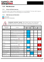
Page 6: ...tions and advice on handling this material see section 6 2 2 2 Siting and Setting Up Place the product on a level surface in a well ventilated area Site away from other sources of heat and on a non flammable surface that is resistant to accidental spillage or hot materials The surface on which the equipment is mounted should be stable and not subject to movement or vibrations The height of the mou...

Page 7: ...that the product is placed in such a way that it can be quickly switched off or disconnected from the electrical supply Under no circumstances should any objects be placed on top of the product Always ensure that any vents on the top of the product are clear of any obstruction Always ensure all cooling vents and cooling fans if fitted are clear of any obstruction 7 ...

Page 8: ...r transit Please ensure the plastic tie wrap used to fix the arm is removed before operation 1 Remove the back panel of the furnace 2 Locate the tie wrap that has been used to prevent the arm from moving It is marked with a tag as shown in the photograph below 3 Cut the tie wrap and discard 4 Replace the back panel 8 ...

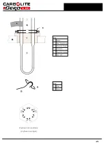
Page 9: ...ely together with other items shown in the list separately packed items BLF Elements 6 Element Clamps 6 Elements Clips 12 Braids 1 set Separators 6 or combined clips and braids may be supplied BLF 3 transit clamps Upper Clamp 1 Remove lower clamp first 2 Remove two M8 nuts and washers supporting plate 3 from underneath 3 Remove plate Lower Clamp 1 Remove bottom M8 nut 2 Remove two M6 bolts 3 Remov...

Page 10: ... to Neutral reversible non polarised or Live to Live Check the product rating label before connection The supply voltage should agree with the voltage on the label and the supply capacity should be sufficient for the current on the label The supply should be fused at the next size equal to or higher than the current on the label This manual contains a table of the most common fuse ratings When the...

Page 11: ... Reversible or Live Live 1 phase L1 Brown to live to either power conductor For USA 200 240V connect L1 N L2 Blue to neutral to the other power conductor For USA 200 240V connect L2 PE Green Yellow to earth ground to earth ground Electrical Connection Details 11 ...

Page 12: ...3 0 Temperature Controller If this product is fitted with a temperature controller instructions are provided separately 12 ...

Page 13: ...he controller setpoint or program unless a time switch is fitted and switched off The heat light glows brightly at first more dimly as the product temperature approaches a program setpoint Over Temperature option only If the over temperature circuit has tripped an indicator on the over temperature controller flashes and the heating elements are isolated Find and correct the cause before resetting ...

Page 14: ...etal oxides react with the silica layer on the surface of the elements and may lead to premature failure Protect the elements from splashes of molten metal and dust when loading the furnace and from fumes developed when melting especially from fluxes Also avoid compounds with a high alkali content The furnace is designed for use up to its maximum temperature in oxidising atmospheres but can be ope...

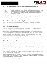
Page 15: ...roduct is designed for heating and cooling at controlled rates The heating and cooling rates can be set in the temperature programmer The programmer enables the furnace to heat or cool at slower rates as desired and variable hold dwell periods can be programmed as required The programmer is used in conjunction with a phase angle thyristor power controller which incorporates a current limit potenti...

Page 16: ... height of the work piece it may be necessary to hold the crucible up in the chamber when placing the work piece on the hearth ensure that appropriate tongs are available before starting Clamp Option This option assists the placing of the crucible over tall work pieces The clamp is provided in the form of a support shelf which can be fitted to a hinge on the case and a pair of insulated tongs With...

Page 17: ...mergency stop button to prove that it functions correctly Safety Switch Function Check that the hearth will not raise or lower with the cage open Safety Switch Function Electrical measurement Over Temperature Safety Circuit if fitted Set an over temperature setpoint lower than the current displayed temperature and check for an over temperature alarm as detailed in this manual Over Temperature Safe...

Page 18: ...e standard required Operational Check Check that all functions are working nor mally Operational Check Thorough inspection and report incor porating a test of all functions Performance Element Circuit Electrical measurement Power Consumption Measure the current drawn on each phase circuit 18 ...

Page 19: ...e maintenance of furnace and oven products both at the Carbolite Gero factory and at customers premises throughout the world A telephone call or email often enables a fault to be diagnosed and the necessary parts to be despatched In all correspondence please quote the serial number and model type given on the rating label of the product The serial number and model type are also given on the back o...

Page 20: ...ch control power to the elements are fitted with an adjustable resistor which is factory set to limit the maximum current supplied In the event of a change of supply voltage or the fitting of a new thyristor further adjustment may be required The maximum element currents for this model are listed in section 9 0 Please contact Carbolite Gero for further information 20 ...

Page 21: ...cant level of airborne dust from these materials but much higher levels may be encountered during maintenance or repair Whilst there is no evidence of any long term health hazards it is strongly recommended that safety precautions are taken whenever the materials are handled Exposure to fibre dust may cause respiratory disease When handling the material always use approved respiratory protection e...

Page 22: ...y or may not be fitted If any fuse has failed it is advisable for an electrician to check the internal circuits Replace any failed fuses with the correct type For safety reasons do not fit larger capacity fuses without first consulting Carbolite Gero The fuses are located at the cable entry point Remove the back panel or control box back panel to gain access to the fuses 6 6 Thermocouple Replaceme...

Page 23: ... screws that hold each of them in place Care should be taken as insulation may fall if unsupported during the removal of the sections Once the insulation sections have been removed pass the tube up through the hole in the bottom of the furnace and locate within the recess of the furnace roof Once correctly located re fit the insulation sections and the corresponding brackets Re fit the stainless s...

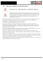
Page 24: ... tool provided depending on the type of clip or remove the combined clips and braids if supplied Lift out the old element and the insulation block handle the block with care as it is fragile Remove the clamps Handle the heating elements with extreme care as they are VERY FRAGILE Also avoid touching the heating surface the thin part of the element Carefully unpack the elements and insert them into ...

Page 25: ...Key A Braid B Roof Insulation C Element block D Element E Element Clamp See text Key A Clip B Braid Element Connections 3 phase example 25 ...

Page 26: ...Use of Clip Tool The distance from the top of the element clamp to the top of the element should be 40 mm Larger clips require the clip tool comprising two levers 1 Clip tool 2 Apply hand pressure 26 ...

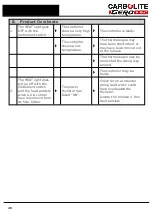
Page 27: ...n or has a wiring fault The controller shows a low temperature The door switch may be faulty or need adjustment The thyristor fuse may have blown The power thyristor could be failing to switch on due to internal failure faulty wiring from the controller or fault controller There are no lights glowing on the controller Check the supply fuses and any fuses in the product control compartment The cont...

Page 28: ...t or may have been moved out of the furnace The thermocouple may be connected the wrong way around The controller may be faulty 2 The HEAT light does not go off with the instrument switch and the fault persists when a 2 A control fuse is removed from its fuse holder The power thyristor has failed ON Check for an accidental wiring fault which could have overloaded the thyristor Isolate the furnace ...

Page 29: ...8 0 Wiring Diagrams 8 1 195 1 1013 29 ...

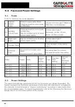
Page 30: ...e fitted Recommended if cable fitted See rating label for current See table below for fuse rating Model Phases Volts Supply Fuse Rating Type Thyristor Fuse Rating Current Limit Element Circuit BLF 17 3 1 phase 208 V 32 A NS32 50 A 80 A BLF 17 3 1 phase 200 V 32 A NS32 50 A 80 A BLF 17 3 1 phase 230 V 32 A NS32 50 A 80 A BLF 17 3 1 phase 240 V 32 A NS32 50 A 80 A BLF 17 3 2 phase 380 V 16 A NS32 50...

Page 31: ... the power limit parameter in the controller OP Hi should be 100 for this product Please refer to the rating label for product specific information Please refer to the rating label for product specific information 31 ...

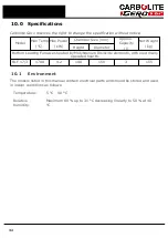
Page 32: ...ight Diameter Bottom Loading Furnaces heated by Molybdenum Disilicide elements with electrically operated hearth BLF 17 3 1700 4 2 190 150 3 155 10 1 Environment The models listed in this manual contain electrical parts and should be stored and used in indoor conditions as follows Temperature 5 C 40 C Relative humidity Maximum 80 up to 31 C decreasing linearly to 50 at 40 C 32 ...

Page 33: ...Notes Service Record Engineer Name Date Record of Work ...

Page 34: ... us at the address below or ask your nearest stockist For preventive maintenance repair and calibration of all furnace and oven products please contact Carbolite Gero Service Telephone 44 0 1433 624242 Fax 44 0 1433 624243 Email ServiceUK carbolite gero com Carbolite Gero Ltd Parsons Lane Hope Hope Valley S33 6RB England Telephone 44 0 1433 620011 Fax 44 0 1433 621198 Email Info carbolite gero com...

Reviews: