
Duct heater DH-R
16
tel. (22) 751 95 50
www.venture.pl
fax. (22) 751 22 59
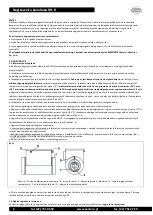
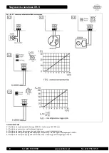
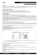
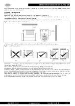
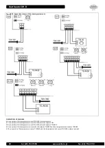
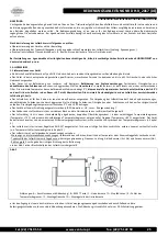
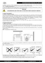
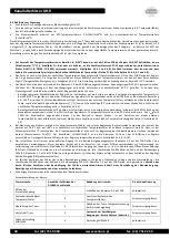
Fig. 4
Recommended assembly order
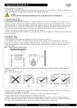
It is recommended to ensure, between the channel inlet and the system components such as elbows, reducers and fan, a distance of
minimum 3 channel width.
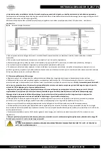
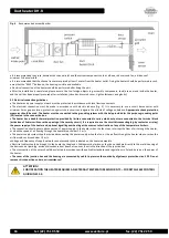
It is recommended that the channel sensor was placed at least 1 meter from the heater outlet. Fixing the heater should be performed in such
a way that the "RESET" button on the housing is visible and available.
Electrical connection of the heater should be performed after fixing the unit.
After the installation is completed, please ensure, that no foreign objects (e.g. assembly components, tools) are near and inside the heater,
and the unit has been properly secured after installation (closed and secured cover, tighten fasteners and glands).
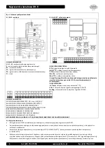
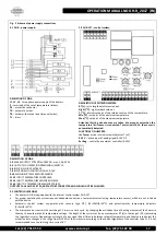
3.2 Electrical connection guidelines
The heater and power supply network must be protected in accordance with local law requirements
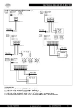
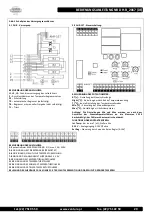
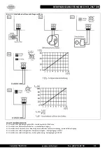
The electrical connection must be made in accordance with electric scheme (Fig. 5). It is necessary to use a circuit disconnector with
minimum 3mm gap insulation, protection against short circuits and against the effects of voltage unbalance.
Appropriate shock protection
measures should be used. The heater must be connected to the grounding system with the help provided for this purpose grounding point
(PE) located in the connection box.
The heater has a double thermal protection provided by limiters connected in series, which outputs are connected to the terminal block
(activation of limiters will cause the opening of the security circuit). It is required to use the circuit disconnecting (eg. by contactor or relay)
the power supply of the heater and, optional signalling overheating at the moment of activation of any of the temperature limiters.
The connection should ensure disconnection of power supply to the heater when the fan stops, interrupt the flow of air through the heater,
or when the speed of air flowing through the heater drops below 1.5 m / s.
The power supply system should provide disconnecting the power supply when the fan, or the air flow through the heater stops or when the
air flow velocity drops below 1,5 m/s.
Voltage and frequency of supply network cannot exceed those indicated on the heater nameplate.
Electrical cables should be brought to the heater by the glands. Cables must be laid so as they do not adhere directly to the metal housing of
the device and a liquid (eg. accidental condensation) does not run over them in the direction of the junction box.
The cross section of the wires should be selected in accordance with applicable standards and regulations in Poland, based on the power of
the heater.
The cover of the junction box and the housing are connected by cable to preserve the continuity of galvanic protection circuit PE. Do not
remove this connection under no circumstances!
ATTENTION!
FOR OPERATION THE HEATER REQUIRES AN EXTERNAL TEMPERATURE SENSOR NTC – FOR DETAILS SEE CONTROL
GUIDELINES 3.3.