8
VUTR 250/350/650 P/P2/PE/P2E EC
www.ventilation-system.com
DESIGN AND OPERATING PRINCIPLE
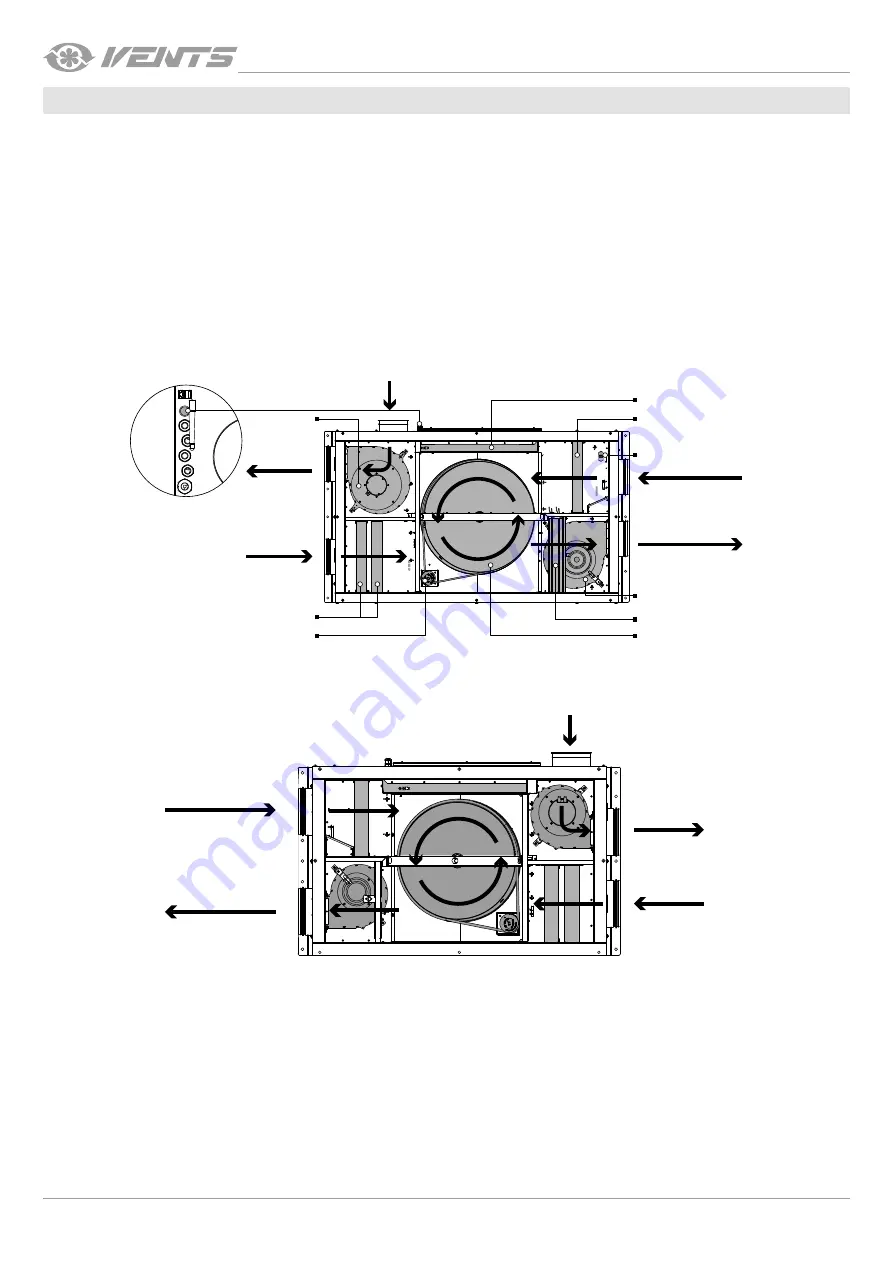
The unit has the following operating principle:
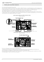
Warm stale extract air from the room flows to the unit, where it is filtered. Then the air is moved through the rotary heat exchangers and is
exhausted outside with the exhaust fan. Clean cold air from outside is moved to the supply filter. Then filtered air flows through the rotary
heat exchanger where it is warmed up to the pre-set temperature value and is moved to the room with the supply fan.
Heat energy of warm extract air is transferred to clean intake fresh air from outside and warms it up.
Heat recovery minimizes losses of electric energy and space heating expenses in cold seasons and cooling expanses in warm seasons.
An exhaust kitchen hood may be optionally connected to the unit. The kitchen hood should be equipped with an air valve. The valve
closes the exhaust duct when the kitchen hood is switched off.
Right-handed modification (VUTR 350 P(2)E EC R A21)
(service side view)
Supply air
Extract air
From the exhaust hood
Heater
Rotary heat exchanger
Extract fan
SETUP MODE button
Extract filter
Control unit
Supply filter
Rotary heat exchanger drive
Humidity sensor (optional)
Supply fan
Intake air
Exhaust air
Left-handed modification (VUTR 350 P(2)E EC L A21)
(service side view)
From the exhaust hood
Intake air
Exhaust air
Supply air
Extract air
The unit is a framework construction made of rigidly fixed panels.
The panels are made of aluzinc and galvanized sheets, internally filled with a heat- and sound-insulated layer of mineral wool.
The air handling unit is equipped with quick-detachable service panels for filter replacement.
Route power and ground cables through the screwed cable glands to connect those to the terminal block located in the control unit.
The wiring diagram is shown on the control unit side panel.


