


7
www.ventilation-system.com
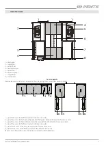
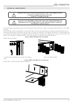
UNIT DESIGN
1
1
4
5
6
7
8
2
4
3
1 – drain pipe
2 – supply fan
3 – extract filter
4 – heat exchanger
5 – extract fan
6 – bypass damper
7 – supply filter
8 – control unit
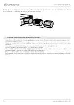
Service panels
Removable service panels are located on the unit casing for accessing the unit assemblies.
1
5
5 6
6
2
3
4
1 – panel for access to the filter (located on the service side)
2 – panel for access to the heat exchanger and the bypass damper (located on the service side)
3 – panel for access to the control unit and the terminal block (located on the service side)
4 – panel for access to the filter (located on the service side)
5 – panels for access to the fans (located at the bottom of the unit)
6 – panels for access to the filters (located at the bottom of the unit)
Panels 1-5 are fixed with screws. Panels 6 are secured with thumbscrews.


