background image

Installation 

Sentinel Kinetic MVHR Installation & Commissioning 

21


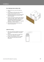
Floor Mounting Sentinel Kinetic Plus 

1. 

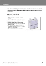
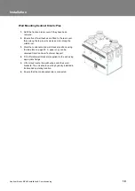
Refit the front and rear covers if they have been 
removed.  

2. 

Ensure that a secure, firm, flat and level surface is 
provided to place the Kinetic Plus unit on. 

3. 

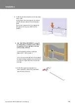
If required a board may be screwed to the base of the 
unit allowing the assembly to be screwed to joists, 
flooring or equivalent. 

4. 

Use (the wall mounting) screws through the diameter 5 
mm holes in the base.  If longer screws are used due 
to the thickness of the board do not allow these to 
project more than 45 mm into the expanded 
polystyrene.  The screws should go into the expanded 
polystyrene by a minimum of 35 mm. 

5. 

The unit should now be physically installed in its 
intended operating location. 


Attach the ducting: 

1. 

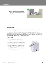
Always use a short piece of flexible duct 100-150 mm 
long, extended to its full length when connecting to 
ductwork. 

2. 

Securely connect this ducting to the spigots using 
worm-drive clips, cable ties or duct tape. 

3. 

Insulate any ducting passing through an unheated 
space to prevent any heat losses and surface 
condensation. 


Summary of Contents for Sentinel Kinetic B 438222

Page 1: ...s reserved Sentinel Kinetic MVHR and Kinetic Plus MVHR Installation Commissioning Stock Ref N 438222 Kinetic B 443319 Kinetic BH 438342 Kinetic V 443028 Kinetic Plus B 443029 Kinetic Plus CV CP PLEASE RETAIN THESE INSTRUCTIONS WITH THE PRODUCT ...

Page 2: ...ED TO THE BUILDING S FOUL WATER DRAINAGE SYSTEM 11 IF THE EXTRACT GRILLE ASSOCIATED WITH THE UNIT IS SITED IN A ROOM CONTAINING A FUEL BURNING APPLIANCE THE INSTALLER MUST ENSURE THAT AIR REPLACEMENT IS ADEQUATE FOR BOTH APPLIANCES 12 CERTAIN APPLICATIONS MAY REQUIRE THE INSTALLATION OF SOUND ATTENUATION TO ACHIEVE THE SOUND LEVELS REQUIRED 13 THE UNIT MUST NOT BE CONNECTED DIRECTLY TO A TUMBLE DR...

Page 3: ...28 Control Unit Screens Summary 29 Commissioning Screens 30 Maintenance 37 Caring for the Unit 40 Filter Maintenance 40 12 Monthly Maintenance 40 Spares 41 Troubleshooting 42 Diagnosing a Problem 42 Appendix Options and Accessories 43 CO2 Temperature Sensor 43 Normal Boost switch 43 Humidistat 43 System Cooker Hoods 43 Wireless Boost Switch 44 Remote Wired Control 45 UK Building Regulations Part F...

Page 4: ...ntinel Kinetic B with summer bypass 443319 Sentinel Kinetic BH with summer bypass and integral humidity sensor 438342 Sentinel Kinetic V without summer bypass 443028 Sentinel Kinetic Plus B with Summer Bypass and integral humidity sensor 443029 Sentinel Kinetic Plus CV CP currently not available Accessories 441838 Sentinel Kinetic Plug in integral humidity sensor 441865 Wireless enable kit consist...

Page 5: ... nominal 50 Hz nominal Supply Fuse 3 A located in fused spur 3 A located in fused spur Product Fuse 2 A located on main PCB 2 A located on main PCB Rated Power 150 W max 190 W max Physical Height excluding spigots 550 mm 630 mm Width excluding spigots 550 mm 775 mm Depth 285 mm 524 mm including filter flap hinge protrusion Weight 15 kg 24 kg Spigot diameter 125 mm 150 mm Condensate pipe diameter 2...

Page 6: ... Specification Sentinel Kinetic MVHR Installation Commissioning 6 360 140 ø125 550 285 Allow clearance to remove filter 456 550 650 Figure 3 Sentinel Kinetic Dimensions Figure 4 Sentinel Kinetic Plus Dimensions ...

Page 7: ...ol your room then the SBP will open and the unit will supply cooler air to your room If the room is cooler than the set indoor temperature i e you need the room heating and the outdoor air is warmer than the actual room temperature i e the outdoor air could heat your room then the SBP will open and the unit will supply warmer air to your room Note that the above only applies whilst the outdoor air...

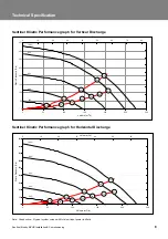
Page 8: ...unit input power in Watts 0 50 100 150 200 250 300 350 400 450 0 50 100 150 200 250 Volume l s Static Pressure Pa 0 50 100 150 200 250 300 350 400 450 0 10 20 30 40 50 60 49 26 12 89 118 54 18 25 38 97 75 Volume m3 h 20 40 60 80 100 0 50 100 150 200 250 300 350 400 0 50 100 150 200 250 300 Volume m3 h Static Pressure Pa 0 50 100 150 200 250 300 350 400 450 0 10 20 30 40 50 60 70 80 53 96 27 13 20 ...

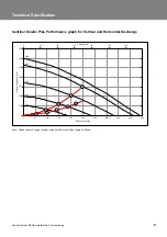
Page 9: ... Vertical and Horizontal Discharge Note Graph shows 2 typical system curves with total unit input power in Watts 0 100 200 300 400 500 600 700 0 50 100 150 200 250 300 350 400 450 500 Volume m3 h Static Pressure Pa 0 100 200 300 400 500 600 700 0 20 40 60 80 100 120 Volume l s 8 14 41 66 140 83 42 21 24 20 40 60 80 100 ...

Page 10: ... for the site meet or exceed the requirements detailed in the Technical Specification on page 5 Read and observe the safety notices listed in Warnings and Safety Information on page 2 Unit Installation The Sentinel Kinetic unit is typically installed on a wall in a kitchen storage cupboard roof void or similar It will fit in a 600 mm external x 300 mm deep internal kitchen wall cupboard The Sentin...

Page 11: ...iated Control Unit Panel and the rear cover and associated Cable Inlet Plate rotating the unit chassis and covers through 180 degrees and then re attaching them This moves the condensate drain exit from the right rear corner of the unit to the left front corner of the unit when viewed from the front viewing the Control Unit The arrow labels on the top edge of the Covers should be correctly matched...

Page 12: ...ect the ribbon cable 7 Disconnect the 4 way connector 8 Remove the 2 screws and detach the rear Cable Inlet Plate Note that the grommets shown may be replaced by easy knock out positions If these are required ensure that you use a grommet or gland to protect against potential water ingress 7 Re attach the Cable Inlet Plate on the opposite side of the unit ...

Page 13: ...nt and rear covers off the unit 12 For vertical discharge condensate connection continue on page 13 or for horizontal discharge condensate connection go to page 14 Vertical Discharge Condensate Installation Note The 22 mm diameter condensate pipe is suitable for standard 22 mm plastic push fit fittings and can be connected vertically underneath the unit or horizontally at the rear To install the v...

Page 14: ...there is a minimum 3 degree fall to allow condensate drainage Both left hand and right hand condensate drain pipes are supplied for use as appropriate depending on the orientation of the unit 4 Go to Spigot Installation on page 16 Horizontal Discharge Condensate Installation To install the condensate horizontal discharge 1 For horizontal discharge remove the front cover and locate the condensate s...

Page 15: ...a little from this guidance 4 N B SEE WALL MOUNTING on page 16 for information on marking out the wall for the position of the condensate drain and wall mounting brackets Fit Vertical discharge 32mm waste pipe fitted with 22 32mm reducer Fit a U bend condensate drain to the building s foul water drainage system and ensure there is a minimum 3 degree fall to allow condensate drainage 5 Fit the 180 ...

Page 16: ...K model or for diameter 180 mm ducting rest of EU model The diameter 180 mm spigots come complete with self adhesive foam adaptors to enable it to be used with either diameter 180 mm ducting or diameter 200 ducting These foam adaptors are to be fixed to the outside of the spigot for diameter 180 mm ducting To move the spigots 1 Remove the spigot by unscrewing the screw s securing it to the chassis...

Page 17: ...tic 1 Refit the front and rear covers if they have been removed 2 Ensure four off wall bushes are fitted to the rear cover across the middle and lower screws 3 Mark the condensate and wall bracket positions 4 Fit 2 off metal wall brackets supplied to the wall using appropriate fixings 5 Lift unit and locate the wall bushes onto the 2 wall brackets The unit should now be physically installed in its...

Page 18: ...Sentinel Kinetic MVHR Installation Commissioning 18 264 26 316 L H CONDENSATE EXIT 213 R H CONDENSATE EXIT 213 61 61 484 TO CENTRE OF HORIZONTAL SPIGOT CENTRES OF TOP SPIGOTS 370 9 48 Wall Mounting Sentinel Kinetic ...

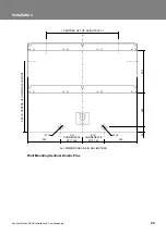
Page 19: ... screws and two along the middle row 3 Mark the condensate and wall bracket positions using the template on page 20 A paper copy can be obtained from Vent Axia Technical Support 4 Fit 2 off metal wall brackets supplied to the wall using appropriate fixings 5 Lift unit and locate the wall bushes onto the 2 wall brackets The unit should now be physically installed in its intended operating location ...

Page 20: ...nstallation Commissioning 20 CENTRES OF TOP SPIGOTS 520 505 TO CENTRE OF HORIZONTAL SPIGOT R H CONDENSATE EXIT 153 Ø 32 303 245 34 L H CONDENSATE EXIT 153 240 240 Ø 32 ALL DIMENSIONS ARE IN MILLIMETRES Wall Mounting Sentinel Kinetic Plus ...

Page 21: ... holes in the base If longer screws are used due to the thickness of the board do not allow these to project more than 45 mm into the expanded polystyrene The screws should go into the expanded polystyrene by a minimum of 35 mm 5 The unit should now be physically installed in its intended operating location Attach the ducting 1 Always use a short piece of flexible duct 100 150 mm long extended to ...

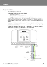
Page 22: ...tector for example detecting a hob being switched on or a temperature sensor for example detecting the flow of hot water Terminal 4 can be used in conjunction with a momentary switch or switches Connect any switches or sensors required to control the unit by connecting to the terminal connectors at the bottom of the control unit as shown below and in Table 1 If necessary contact Vent Axia regardin...

Page 23: ...ult Code Screens on page 43 L Mains Live 220 240 V AC 50 Hz input N Mains Neutral 220 240 V AC 50 Hz input EARTH Mains Earth Earthing connector LS Switched Live 220 240 V AC 50 Hz input Connect the Power Supply WARNINGS 1 MAINS SUPPLY VOLTAGES 220 240 V AC ARE PRESENT IN THIS EQUIPMENT WHICH MAY CAUSE DEATH OR SERIOUS INJURY BY ELECTRIC SHOCK ONLY A QUALIFIED ELECTRICIAN OR INSTALLER SHOULD CONNEC...

Page 24: ...front of the Sentinel Kinetic unit The Control Unit provides the user interface for commissioning and monitoring purposes Display The main display is a 16 character by 2 line liquid crystal display LCD with automatic backlight which is turned off to automatically minimise power consumption Normal Airflow 30 Buttons Four buttons on the Control Unit provide the controls for configuring and monitorin...

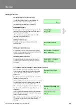
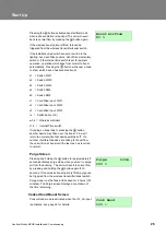
Page 25: ...or Screen The Humidity Sensor screen displays whether the humidity sensor is fitted It is typically displayed for 3 seconds Humidity Sensor Not Fitted Low Airflow Normal Airflow Boost Airflow Screen When the start up screens are finished the low or normal screen is displayed showing operating status Low Airflow X or Normal Airflow X or Boost Airflow X The Normal screen displays the rate of normal ...

Page 26: ...ut S W3 ls Switched live LS w1 4 Wireless controller c1 3 Internal Time switch If running on boost due to pressing the button another device may take over the boost Flow will return to normal when that device switches off If a number of different devices are calling for boost flow the unit will run at boost until the last one has reverted to normal Boost Airflow 50 Purge Screen Pressing and holdin...

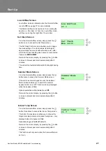
Page 27: ... not automatically switch for daylight saving time Set Clock Mon 12 30 Summer Mode Screen From the Normal Airflow screen simply press the button twice to access the Summer Mode screen If the unit is a summer bypass model the Summer Mode screen enables you to switch the summer bypass control on or off This screen is only displayed when the bypass is fitted Options available are On default and Off R...

Page 28: ...o choose the minimum outdoor temperature at which the bypass will operate in degrees Centigrade only displayed when the bypass is fitted Use this to prevent cold draughts being introduced Selectable range is 5C 20C 14C default Return to the normal display by pressing the button or leave to timeout and return automatically after 2 minutes This function will only work when the Summer Mode is set to ...

Page 29: ...hooting on page 40 Follow good practice when commissioning the unit Ensure that the system is installed according to the system designers intent incorporating any acoustic ducting that all joints are air tight ducting is well supported bends are avoided close to vents and that the vent valves are fully open at the start of the commissioning process The following is attached to the unit and should ...

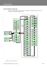
Page 30: ...e Defaults No PIN number not set PIN number set if fitted Ventwise Input 2 Load pot 60 Ventwise Input 3 Load pot 60 if fitted if fitted V Language English Airflow Units Wireless Control Not Fitted Humidity Sensor Not Fitted Normal Airflow 30 Set Clock Mon 12 30 Summer Mode On Indoor Temp 21 C Purge 120m 100 Boost Airflow 50 Press for 5 s Press for Boost Timeout after 2 minutes Press Start up Scree...

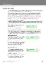
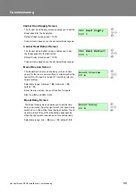
Page 31: ...play will resume if no buttons are pressed for two minutes Security PIN Screen If a security PIN code has been previously set this screen will display Enter the PIN using and buttons Security PIN Note Whilst displaying the Low Normal Boost Supply Low Normal Boost Extract screens the fans will run at the displayed flow and the bypass will remain shut The two minute automatic return to normal displa...

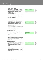
Page 32: ...l speed 30 See graph on page 8 9 for setting the Extract airflow The Normal speed cannot be set below Low speed or above Boost speed setting Normal Extract 30 Low Supply Screen The Low Supply screen enables you to set the Low airflow speed for the Supply fan in order to balance out any differences in ductwork or other installation features Default Low speed 20 See graph on page 8 9 for setting the...

Page 33: ...ost Overrun Screen The Boost Overrun screen enables you to set a time period for the fans to boost airflow in minutes after the light switch LS input is turned off It will then return to normal airflow Selectable range minimum 00 maximum 25 default 15 Boost Overrun screen does not function for inputs S W1 to S W3 and SW4 SW5 Boost Overrun 15 m Boost Delay Screen The Boost Delay screen enables you ...

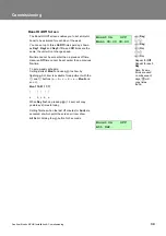
Page 34: ...et earlier than a previous On time To set a weekly schedule Setting starts at Mon1 and uses to show by flashing which item is available for adjustment with the and buttons a b c d e Mon2 and so on Mon1 10 01 11 11 a b c d e When Day flashes pressing 2 sec will copy yesterday s times to today Setting finishes when the last off minutes for Sun3 are accepted at which point the screen will now show Al...

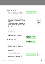
Page 35: ...g 2 sec will copy yesterday s times to today Setting finishes when the last off minutes for Sun are accepted at which point the screen will now show All Set or holding the button for 3 seconds Normal On Off Mon 00 00 00 00 Normal On Off All Set Set Service No Screen The Set Service No screen enables you to enter the telephone number that should be called for service in the event the unit fault Ini...

Page 36: ... runs at a proportional airflow Proportional 1 Humidity For a humidity sensor a percentage value must be entered for boost and normal settings For range and default values see Table 2 below P1 Boost Limit 70 P1 Normal Limit 60 For a CO2 sensor a figure in ppm must be entered for boost and normal settings For range and default values see Table 2 below P1 Boost Limit 2000 ppm P1 Normal Limit 1000 pp...

Page 37: ...ith the Load Pot set to 60 A temperature sensor will trip with hot water at around 40ºC and a current one around 1 5 A Time Pot setting is from 1 to 25 minutes with a default of 20 minutes A one second push on a momentary switch wired to SW4 will run boost for up to 25 minutes The overrun timer can be set from 15 to 30 mins A second one second push will cancel the boost as would a cancel boost sig...

Page 38: ...t forming on the heat exchanger Antifrost Airflow Mode Dryout Screen The Dryout screen enables the fans to be run at max speed for a week before returning to normal operation This feature can help to dry out fresh plaster and paint enabling building work to be completed more quickly Filters may become fouled during this time and should be cleaned or replaced afterwards Available options Off defaul...

Page 39: ...tored by setting the Restore Defaults screen to Yes Restore Defaults No The Security PIN screen enables you top set a four digit personal identification number PIN to access the commissioning screens This screen will show blank if security is disabled and no PIN is used Press to reveal 0000 with the first 0 flashing and use the and buttons to change the selection 0 9 Press again to accept the digi...

Page 40: ... 0 00 on 00 00 off inactive Normal On Off All days set to 0 00 on 00 00 off inactive Set Service No Not set Proportional 1 Humidity Boost Normal 60 CO2 Boost 2000 ppm Normal 1000 ppm Temperature Boost 27 C Normal 17 C Proportional 2 CO2 Boost 2000 ppm Normal 1000 ppm Temperature Boost 27 C Normal 17 C Humidity Boost Normal 60 Vent Wise 1 2 3 Load Pot 60 Time Pot 20 m SW4 Off or with Vent Wise card...

Page 41: ...tic message press and hold the and buttons for 5 seconds 12 Monthly Maintenance Item Action Fan Filters Change the Fan Filters 1 Open the filter flaps and remove the 2 filters 2 Insert the replacement filters 3 Close the filter flaps 4 Reset the automatic message press and hold the and buttons for 5 seconds Unit Heat Exchanger Cell Inspect and clean the unit 1 Isolate the mains power supply 2 Open...

Page 42: ... 438222 442356 Filters 2 per pack non bypass version 438242 441764 Heat Recovery Cell bypass version 438222 441996 Heat Recovery Cell non bypass version 438242 441759 Supply Motor 441760 Exhaust Motor 441776 Summer Bypass 438378 Spigot one per pack SENTINEL KINETIC PLUS SPARES 443351 Filters 2 per pack 443352 Heat Recovery Cell 443353 Supply Motor 443354 Exhaust Motor 443355 Summer Bypass 441418 S...

Page 43: ...or assistance contact the service provider and quote the fault code number The following fault codes numbers may be displayed Code numbers are added together if more than one is detected Table 4 Fault Codes Code Problem 01 Supply Fan not running 02 Extract Fan not running 04 Control PCB 24 V fuse FS1 failure 08 Temperature sensor T1 supply faulty 16 Temperature sensor T2 extract faulty 32 Wired Re...

Page 44: ...in conjunction with other boost controls Humidistats An internal Relative Humidity Sensor PCB 441838 may be used to control airflow The unit adjusts the fan speed proportionally depending on the temperature and relative humidity levels in the extracted air whilst avoiding nuisance tripping at night time when temperatures drop and relative humidity naturally rises The unit does not just look for re...

Page 45: ...reless Switch s can be used to control any one unit The Wireless Switch address needs to be different for each Switch in a system 4 Accessories can be connected to the volt free and light switch connections so that the transmitter sends a boost signal on the accessory s behalf The LED light above the button will illuminate when a button is pressed Pressing the button will send a signal wirelessly ...

Page 46: ...g the unit 2 To fit the Wired Remote Control remove the Front Rear and Electrical covers using the cable assembly supplied insert the RJ11 plug into the socket marked BMS and feed the remaining cable through cable inlet plate refit all covers 3 Connect the cable assembly 4 wires numbered 1 to 4 to the Remote Control terminal block and mount onto a single gang recessed wall box with the 2 screws pr...

Page 47: ......

Page 48: ... Crawley West Sussex RH10 9JA SALES ENQUIRIES Tel 0844 8560590 Fax 01293 565169 TECHNICAL SUPPORT Tel 0844 8560594 Fax 01293 532814 For details of the warranty and returns procedure please refer to www vent axia or write to Vent Axia Ltd Fleming Way Crawley RH10 9YX 439817 L 2010 Vent Axia Limited All rights reserved 1210 ...

Reviews: