


operation the fan enters calibration mode to determine the most efficient
mode of operation.
Calibration Reset
In some circumstances it may be necessary to reset the calibration
settings (if the fan was covered to prevent dust/damage/or poor weather
outside).
Reset the calibration by configuring the fan for wall or duct mode (F-0 or
F-1), turn the product off and on and re-configure back to CV mode
(F-2). The fan will calibrate after 15 minutes or by holding the pullcord for
5 seconds.
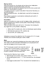
Pullcord
Switches the fan from trickle to boost (for boost overrun time)
o
If the overrun time has been set to 0 (disabled), a default
overrun duration of 5 minutes will take place.
This will override LS comfort mode, boosting the fan immediately
An activation when a Pullcord/LS (Light Switch) boost is already
active shall cancel overrun timer (RH boost sources remain
unaffected)
Data Logger Menu
* When the display is rotated the decimal point will no longer display; eg.
055 represents 5.5KWh
Cutting the power to the fan will not erase the stored data.
To reset
the data, hold pullcord for 14 seconds while in the data logger menu.
Display text
Description
tot run 00y 00d
Total run time in years and days
Tri run 00y 00d
Trickle speed run time in years and days
Boo run 00d
Boosted run time in days
rhu run 00d
Humidity boosted run time in days
tot EnErgy 00.0
Total Energy used displayed in KWh*
24h EnErgy 00
Energy used in last 24 hours displayed in Wh