background image


Fig.2 


Fig.3 


2.0 Site Requirements 

2.1 Information 

1. The unit is designed for installation in 
external walls with a thickness of up to 310mm. 
For wall thicknesses above 310mm, the ‘L’ 
version of the appropriate model must be used 
(see page 12 ). The ‘L’ models are suitable for wall 
thicknesses up to 425mm. 
 
2. The unit must be sited and connected by a 
suitably competent person and be in 
accordance with current U.K. Building 
Regulations and I.E.E. Wiring Regulations (BS 
7671). 
 
3. The unit must be installed in conjunction with 
the separate power supply supplied, 
which is intended for permanent connection to 
the mains electrical supply. The unit and the 
power supply are intended for fixed 
wiring installation. 
 
4. The power supply requires free air 
circulation for effective operation It must not be 
recessed into the mounting surface or covered 
with any form of insulation, which might be used in 
a ceiling or roof void. The unit must be sited such 
that the ambient temperature will not exceed 40°C. 
please ensure that the air vents on the enclosure 
are not blocked or covered up. 
 
5. Wiring to the unit in the U.K. must be via 
a switched fused spur. 
 
6. The spur should have a minimum contact gap  
of 3mm in all poles. 
 
7. Ensure that the mains electrical supply is 
compatible with the rating label attached to the 
product. 
 
8. The unit must be sited such that the ambient 
temperature will not exceed 40°C. 
 
9. Do not site the appliance in the vicinity of 
excessive levels of airborne oil or grease. or 
directly over a cooker. 
 
10. If the unit is installed in a room containing a 
fuel burning appliance, the installer must ensure 
that air replacement is adequate for both 
appliances. 
 
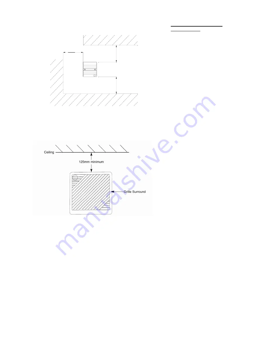
11. The unit must not be installed at a level 
below 500mm from the floor. 
 
12. The internal grille surround must be sited at 
least 125mm away from the room ceiling (Fig. 3). 
and 300mm away from any adjacent vertical 
surface. 
 
13. The external cowl of the unit must be sited 
at least 500mm away from any flue of gas or 
solid fuel appliances. This is to avoid back flow 
of gases entering the room. 
 
14. All safety regulations and requirements 
must be strictly followed to prevent hazards to 
life and property both during and after 
installation and during subsequent maintenance 
or servicing. 
 
15. Ensure the mains electrical supply is 
switched off before commencing installation or 
maintenance. 

2.0 Site Requirements


50mm minimum

50mm minimum

50mm minimum

Summary of Contents for HR25 Solo

Page 1: ...covery Unit Installation and Wiring Instructions Stock Ref N 372261A HR25 372262A HR25H 372263A HR25P 372264A HR25L 372265A HR25LH 372266A HR25LP PLEASE READ INSTRUCTIONS IN CONJUNCTION WITH ILLUSTRATIONS PLEASE SAVE THESE INSTRUCTIONS ...

Page 2: ...372268 2 1 0 Introduction 3 2 0 Site Requirements 4 3 0 Installation 5 4 0 Maintenance 13 5 0 Short Parts List 14 Section Page Contents ...

Page 3: ... provides up to 84 heat recovery from the stale extracted air 4 The range of products is as follows HR25 The HR25 is fitted with a pull cord switch which provides a twin speed control function HR25H The HR25H is fitted with an adjustable humidity sensor which automatically switches between its high and low settings depending on the relative humidity in the room of installation HR25P The HR25P has ...

Page 4: ...U K must be via a switched fused spur 6 The spur should have a minimum contact gap of 3mm in all poles 7 Ensure that the mains electrical supply is compatible with the rating label attached to the product 8 The unit must be sited such that the ambient temperature will not exceed 40 C 9 Do not site the appliance in the vicinity of excessive levels of airborne oil or grease or directly over a cooker...

Page 5: ...r fixing holes and the mounting hole 4 Cut the mounting hole to a diameter of 152mm 6 using a core drill Ensure that there is a slight fall on the hole from inside to outside Fig 4 5 Drill and plug the four fixing holes Install the fixed cable runs using mini trunking or via concealed installation A 3 core red white and black low voltage cable is supplied for connections between the unit and the p...

Page 6: ...e supplied to the red white and black low voltage supply via the terminal block Fig 7 NOTE Red is positive high speed white is positive low speed and black is negative This polarity must be maintained at the unit connections HR25 HR25L ONLY The HR25 HR25L units are factory set to opearate continuously at high or low speed via a pull cord switch Two alternative settings can also be achieved by disc...

Page 7: ...fixing screws provided 11 Remove the control cover by undoing the two retaining screws Fig 14 12 Strip the low voltage cable sheath back 40mm from the end and separate the three individual wires 13 Connect the wires to the terminal block Connect red to red white to white and black to black Fig 13 14 14 Ensure that the low voltage cable is routed through the divider slot Fig 14 15 Reassemble in rev...

Page 8: ...to red white to white and black to black Fig 23 14 Ensure that the low voltage cable is routed through the divider slot Fig 24 15 The HR25H unit is factory set to switch between high or low speed Two alternative settings can also be achieved by changing the position of the jumpers on the control board Fig 23 1 Off Low speed 2 Off High speed 3 Low High speed continuously running 16 The switching po...

Page 9: ...th back 40mm from the end and separate the three individual wires 13 Connect the wires to the terminal block Connect red to red white to white and black to black Fig 28 14 Ensure that the low voltage cable is routed through the divider slot Fig 29 15 The HR25P unit is factory set to switch between high or low speed Two alternative settings can also be achieved by changing the position of the jumpe...

Page 10: ...erate if connected in any other way b The purple white connector determines the unit mode and should be placed on to CON 5 as follows Delayed Action Middle and Top pin Fig 32 Direct Action Bottom and middle pin Fig 33 Note In either mode the white wire should be on the lower pin The unit will not operate if the connector is fitted upside down 19 Replace the control cover with the two securing scre...

Page 11: ...ires Fig 35 2 Carefully withdraw the heat exchanger from the unit Fig 36 3 Slide the inner tube out of the unit by pushing the motor housing Fig 37 4 Remove the plastic ring and rubber seal from the outer tube Fig 38 Fig 35 Fig 36 Fig 37 Fig 38 Red and Black Motor Wires Control Cover Heat Exchanger Motor Housing Inner Tube Chassis Rubber Seal Plastic Ring Outer Tube ...

Page 12: ...to prevent damage Carefully cut the excess off the tube Fig 41 13 Remove any burrs from the tube 14 Reassemble the tubes in reverse order ensuring that the two motor wires are located back in the wiring tunnel and that the tunnel is aligned with the wiring slot in the chassis Fig 42 15 Replace the heat exchanger according to the Inside Outside labels The recess in the heat exchanger outer must be ...

Page 13: ...hanger Fig 45 46 5 Wash the grille surround filter and heat exchanger in warm water using a mild detergent and dry thoroughly NOTE Keep water away from all electrical components and wiring within the unit If it is not possible to fully clean the filter it must be replaced see short parts list on page 15 for part number 6 Reassemble in reverse order ensuring the divider board seals against the heat...

Page 14: ...1 2 3 4 Parts List 5 0 Spares list 5 1 Spares List Key No Description Part No 1 Filter pack of 4 370412 2 Heat Exchanger 372329 3 Power supply unit 447249 4 Rubber seal 371297 ...

Page 15: ......

Page 16: ...n modified or repaired by any person not authorised by the company IF CLAIMING UNDER TERMS OF GUARANTEE Please return the complete product carriage paid to your original supplier or nearest Vent Axia Centre by post or personal visit Please ensure that it is adequately packed and accompanied by a letter clearly marked Guarantee Claim stating the nature of the fault and providing evidence of date an...

Reviews: