


14
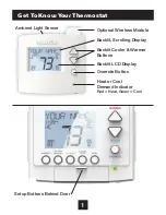
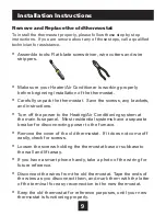
Installation Instructions
Sample Wiring Diagrams
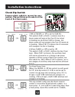
Heat Pump Systems
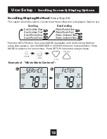
Residential & Commercial
Heat Pump
with
‘O’ Reversing Valve
5 Wire, 1 Stage Cooling, 1 Stage Heat
R 24VAC Power
C 24VAC Common
W1/O/B Reversing Valve
Y1 1st Stage Compressor
(Cool or Heat)
G Fan
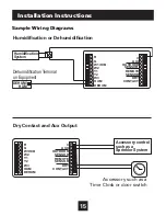
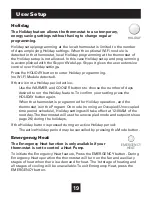
Residential & Commercial
Heat Pump
with
‘O’ Reversing Valve.
8 Wire, 2 Stage Cooling, 4 Stage Heat
R 24VAC Power
C 24VAC Common
W1/O/B Reversing Valve
W2 3rd Stage Heat
W3 4th Stage Heat
Y1 1st Stage Compressor
(Cool or Heat)
Y2 2nd Stage Compressor
(Cool or Heat)
G Fan
Setup Step 24 is set to 2
(Number of Compressor Stages)
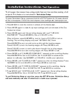
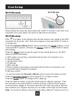
Residential & Commercial
Heat Pump
with
‘O’ Reversing Valve
6 Wire, 1 Stage Cooling, 2 Stage Heat
R 24VAC Power
C 24VAC Common
W1/O/B Reversing Valve
Y1 1st Stage Compressor
(Cool or Heat)
W2 Aux Heat
G Fan
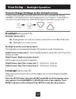
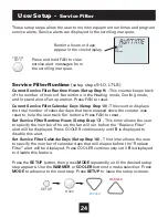
Residential & Commercial
Heat Pump
with
‘O’ Reversing Valve.
7 Wire, 2 Stage Cooling, 3 Stage Heat
R 24VAC Power
C 24VAC Common
W1/O/B Reversing Valve
W2 3rd Stage Heat
Y1 1st Stage Compressor
(Cool or Heat)
Y2 2nd Stage Compressor
(Cool or Heat)
G Fan
Setup Step 24 is set to 2
(Number of Compressor Stages)
1
GAS
O
GAS/EL
ELEC
B
HP
ON
23
1
GAS
O
GAS/EL
ELEC
B
HP
ON
23
1
GAS
O
GAS/EL
ELEC
B
HP
ON
23
1
GAS
O
GAS/EL
ELEC
B
HP
ON
23


