


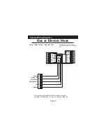


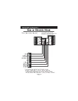
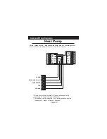
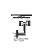


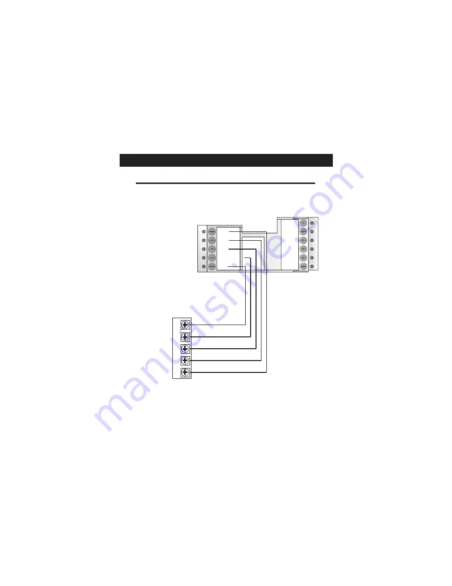
Sample Wiring Diagrams
*
This option must be selected ON during advanced setup
(see page 12, step 3 of Owner’s Manual).
**
This option must be selected O or b during advanced setup
(see page 13, step 4 of Owner’s Manual).
Heat Pump
CK1
GND
RS
RS+5
W2
Y2
C
G
Y1
W1-O-B
R
POWER
R
COMPRESSOR
Y
O
/b
REVERSING VALVE**
COMMON
C
FAN
G
5 Wire, 1 Stage Cooling, 1 Stage Heat-Heat Pump* with O or b reversing valve**.
Residential Heat Pumps, split systems & package units, with no auxiliary heat.
Page 10


