


WWW.VEMMIO.COM
double
switch
MODEL: DS-100
V1.0
INTRODUCTION
Thank you for choosing Vemmio. We welcome you in our cus-
tomer society.
Vemmio Double Switch is a dual relay in-wall module. The prod-
uct works as a transceiver and is a Z-Wave Plus enabled device.
Mini size design lets the module be easily hidden into the wall
box to do not interfere with house decoration. One of many uses
of the Double Switch is to turn on or off the connected fittings
and monitor power consumption in real time. The new smart re-
lay calibration technology can work perfectly with many kinds
of lights like: incandescent, fluorescent and LED lights.
PACKAGE CONTENTS:
•
user manual
•
Double Switch.
KEY FEATURES
Remotely control your equipment and fittings ( On/Off )
Two channels used separately ( 2x 1500 W )
Monitor power consumption in real time
If an overload (>1600-1700 W) is detected, the module auto-
matically cuts off the powered circuit
Mini size design lets the module be easily hidden into the wall
box
SPECIFICATION
Wireless standard
Z-Wave Plus
Frequency
868.40 MHz
Network range
40 m indoor/ 100 m line
of sight
Operating temperature
0°C ~ 40°C
Maximum Load
6.5 A (230 VAC/120 VAC)
(Resistive load)
Operating Voltage
100 to 240 VAC
Control circuits
Two channels 2 x 1500 W
INSTALLATION
DANGER
RISK OF ELECTROCUTION
All work on the device should only be carried out by trained
and skilled electricians. Observe the country-specific regula-
tions.
DANGER
RISK OF FATAL INJURY FROM ELECTRIC CURRENT.
The device has no basic insulation and must therefore be in-
stalled in a way that protects against accidental contact.
DANGER
RISK OF FATAL INJURY FROM ELECTRIC CURRENT.
When installing a wall plate, the distance between the cover’s
fixing brackets or screws and the connections of the flush-
mounted Double Switch must be at least 4 mm once installed.
If the distance is less than 4 mm, a deeper installation box must
be used. The fixing brackets or screws of the cover must not
press against the housing. Only insulated tools may be used for
operation on the device, e.g. an insulated phase tester.
ADDING TO Z-WAVE NETWORK
The Z-Wave button, located in the front casing, can toggle Dou-
ble Switch on and off, add, remove, reset or associate the sensor
to Z-Wave network.
FIRST INCLUSION
Follow the instructions for your Z-Wave certified controller to
enter the desired mode and then follow the instructions from
the table below. When power is applied for the first time, LED
flashes on and off at 0.5 second intervals. It implies that the
Double Switch has not been assigned a node ID and starts auto
inclusion. Auto inclusion will be executed.
Please note: first inclusion may vary depending on your gate-
way - please see gateway manual for details.
Please note: Auto inclusion timeout is 2 minute during which
the node information of explorer frame will be emitted once
every several seconds. Unlike “inclusion” function as shown
in the table below, the execution of auto inclusion is free from
pressing the Z-Wave button.
Function Description
Annotation
No node
ID
The Z-Wave Controller does
not allocate a node ID to the
Switch.
LED 2-second on,
2-second off
Inclusion
*
1. Put your Z-Wave control-
ler into inclusion mode by
following the instructions
provided by the controller
manufacturer.
One press one
flash LED
2. Pressing Z-Wave button
three times within 2 seconds
will enter inclusion mode.
Exclu-
sion
1. Put your Z-Wave control-
ler into exclusion mode by
following the instructions
provided by the controller
manufacturer.
One press one
flash LED
1. Pressing Z-Wave button
three times within 2 seconds
will enter exclusion mode.
3. Node ID has been excluded. LED 0.5s On, 0.5s
Off (Enter auto
inclusion)
Factory
Reset
1. Pressing Z-Wave button
three times within 2 seconds
will enter inclusion mode.
Use this procedure
only in the event
that the primary
controller is lost or
otherwise inoper-
able.
2. Within 1 second, press On/
Off button again for 5 seconds.
3. IDs are excluded.
LED 0.5s On, 0.5s
Off (Enter auto
inclusion)
Associa-
tion
1. The Double Switch is an
always listening Z-Wave de-
vice, so associations can
be added or removed by a
controller at any time.
Or If your controller requires
to have the Double Switch
send a ‘node information
frame’ or NIF for associations,
pressing the Z-Wave button
three times within 2 seconds
will cause the Double Switch
to send
LED one press one
flash
2. There are 3 groups for the
switch
Including a node ID allocated by Z-Wave Controller means
inclusion. Excluding a node ID allocated by Z-Wave Controller
means exclusion.
If the first attempt of exclusion is unsuccessful, please repeat
the process following all steps carefully.
*Please note: Always exclude a Z-wave product before trying
to add it to a Z-Wave network.
ASSOCIATION
Group ID Maximum
Nodes
Description
1
1
For group 1, the Switch will report (1)
ON/OFF status of Relay1 and Relay2
(2) Instant Power Consumption
(Watt) of Relay1 and Relay2 (3) Accu-
mulated Power Consumption (KWh)
of Relay1 and Relay2 to Group1 node.
2
1
For group 2, the Switch will report (1)
ON/OFF status of Relay1 (2) Instant
Power Consumption (Watt) of Relay1
(3) Accumulated Power Consumption
(KWh) of Relay1 to Group2 node.
3
1
For group 3, the Switch will report (1)
ON/OFF status of Relay2 (2) Instant
Power Consumption (Watt) of Relay2
(3) Accumulated Power Consumption
(KWh) of Relay2 to Group3 node.
PHYSICAL INSTALLATION
Choosing a Suitable Location
1.
Do not locate the Double Switch facing direct sunlight, humid
or dusty place.
2.
The suitable ambient temperature for the Double Switch is
0°C~40°C.
3.
Do not locate the Double Switch near combustible substanc-
es or any source of heat, e.g. fires, radiators, boiler etc.
4.
After putting it into use, the body of Double Switch will be-
come a little bit hot.
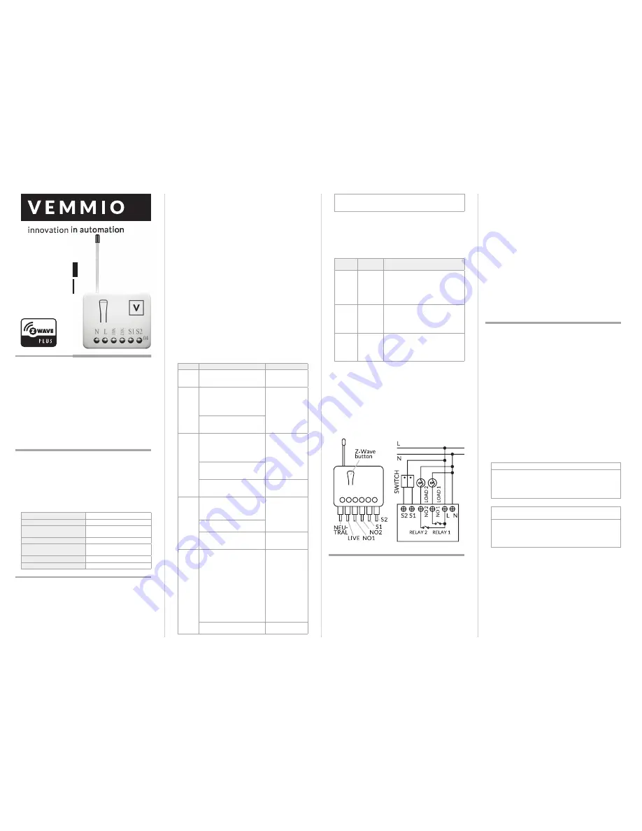
Assembly drawings
MOUNTING
1.
Put the Double Switch into a wall box and connect the wires L,
N to the Double Switch connector L, N.
2.
Connect the wall switch to the Double Switch according to
the above assembly drawings.
3.
To manually turn on the Double Switch, press and release the
Z-Wave button. The LED will flash for 1 second, and the load
plugged into the Double Switch will become active.
4.
To manually turn off the Double Switch, simply press and re-
lease the Z-Wave button. The LED will flash for 1 second and
the load plugged into the Double Switch will become inactive.
FIRMWARE UPDATE OVER THE AIR (OTA)
Double Switch supports Firmware Update Command
Class, it can receive the updated firmware image sent by con-
troller via the Z-wave RF media.
Supported Command Classes
COMMAND_CLASS_ZWAVEPLUS_INFO
COMMAND_CLASS_VERSION_V2
COMMAND_CLASS_MANUFACTURER_SPECIFIC_V2
COMMAND_CLASS_DEVICE_RESET_LOCALLY
COMMAND_CLASS_ASSOCIATION_V2
COMMAND_CLASS_ASSOCIATION_GRP_INFO
COMMAND_CLASS_POWERLEVEL
COMMAND_CLASS_SWITCH_BINARY
COMMAND_CLASS_BASIC
COMMAND_CLASS_SWITCH_ALL
COMMAND_CLASS_ALARM
COMMAND_CLASS_SCENE_ACTIVATION
COMMAND_CLASS_SCENE_ACTUATOR_CONF
COMMAND_CLASS_PROTECTION
COMMAND_CLASS_FIRMWARE_UPDATE_MD_V2
COMMAND_CLASS_MULTI_CHANNEL_V3
COMMAND_CLASS_METER_V3
COMMAND_CLASS_CONFIGURATION
PROGRAMMING
BASIC COMMAND CLASS / BINARY SWITCH COMMAND
CLASS
The Switch will respond to BASIC and BINARY SWITCH com-
mands that are part of the Z Wave system.
1-1 BASIC_GET / BINARY_SWITCH_GET
Since the switch has two relays, the Switch will report its On/
Off state to the Controller by setting Configuration parameter 3.
Configuration parameter 3=1
Report ON when relay 1 ON
Report OFF when relay 1 OFF
Configuration parameter 3=2
Report ON when relay 2 ON
Report OFF when relay 2 OFF
Configuration parameter 3=3 (default)
Report ON when either relay 1 ON or relay 2 ON
Report OFF when both relay 1 and relay 2 OFF
Basic Get Command:
[Command Class Basic, Basic Get]
Basic Report Command:
Report OFF:
[Command Class Basic, Basic Report, Value =
0(0x00)]
Report ON:
[Command Class Basic, Basic Report, Value =
255(0xFF)]
Binary Switch Get Command:
[Command Class Switch Bi-
nary, Switch Binary Get]
Binary Switch Report Command:
Report OFF:
[Command Class Switch Binary, Switch Binary
Report, Value =0(0x00)]
Report ON:
[Command Class Switch Binary, Switch Binary
Report, Value = 255(0xFF)]
1-2 BASIC_SET / SWITCH_BINARY_SET
Since the switch has two relays, the load attached to the Dou-
ble Switch will turn on or off upon receipt of the following
commands from a Z-Wave Controller by setting Configuration
parameter 3.
Configuration parameter 3=1
switch ON and OFF of relay 1
Configuration parameter 3=2
switch ON and OFF of relay 2
Configuration parameter 3=3(default)


