


40 VELUX
®
VELUX
®
41
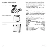
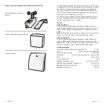
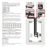
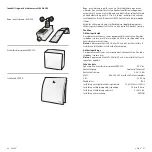
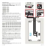
6 polige DIP switch
De variabele wind- en regenparameters en bedieningsinstellingen kunnen
middels een geïntegreerde 6 polige DIP switch ingesteld worden.
Als de sensor gemonteerd en operationeel is, moeten de DIP swit-
ches als volgt ingesteld worden:
Switch 1
OFF
Switch 2
OFF
Switch 3
ON
Switch 4
ON
Switch 5
OFF
Switch 6
OFF
BELANGRIJK:
Fabrieksinstellingen = Testinstellingen.
Opmerking:
In de testinstellingen is de activatie- en uitvalvertraging
uitgeschakeld!
Wanneer de rode LED brand, is de sensor geactiveerd door wind en/of
regen en zal de modulaire lichtstraat gesloten worden.
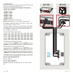
Andere instellingen zijn mogelijk. Het is echter niet aan te raden om de
10 m/s, 12 m/s of 14 m/s windsnelheidinstellingen te gebruiken, door het
risico op van schade aan beslag voordat de modulaire lichtstraat volledig
gesloten is. Aangepaste instellingen zijn op uw eigen verantwoordelijk-
heid.
De DIP switch instellingen voor windsnelheid
Test
On-
geveer
3 m/s
On-
geveer
4 m/s
On-
geveer
6 m/s
On-
geveer
8 m/s
On-
geveer
10 m/s
On-
geveer
12 m/s
On-
geveer
14 m/s
Switch 1
OFF
ON
OFF
ON
OFF
ON
OFF
ON
Switch 2
OFF
OFF
ON
ON
OFF
OFF
ON
ON
Switch 3
OFF
OFF
OFF
OFF
ON
ON
ON
ON
DIP switch instelling voor wind activatie vertraging
2 seconden
5 seconden
Switch 4
OFF
ON
DIP switch instelling voor wind of regen uitvalvertraging
10 minuten
20 minuten
Switch 5
OFF
ON
DIP switch instelling voor bewaken (niet ondersteund door het systeem)
Switch 6
OFF
ON
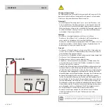
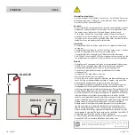
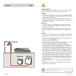
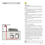
Aansluiting op stroomvoorzieningseenheid KUX 110 en interface
KLF 200
Terminal 1: Voedingsspanning AC / DC
Terminal 2: Voedingsspanning AC / DC
Terminal 3: Relais (C)
Terminal 4: Relais (N/C contact)
Terminal 5: Relais (N/O contact)
Opmerking:
Raadpleeg de instructies voor deze producten die enkel
bedoeld zijn voor installatie binnen in de woning.
ON OFF
1 2 3 4 5
6
1
2
3
4
5
6
A
4 5
3
2
1
B
9 10
8
7
6
17 18 19
− +
Reset
Central unit
6
5
4
3
2
1
1
6
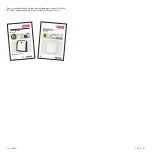
For assembly, remove plug connection from the cover.
Do not mismate during assembly.
LED
on
Terminal 1 = Supply voltage AC/DC
= Relay (arm)
(N/C contact)
6 is internally connected to terminal 2.
Terminal 2 = Supply voltage AC/DC
Terminal 3
Terminal 4 = Relay
Terminal 5 = Relay (N/O contact)
Terminal
1
2
3
4
5
6
AC/DC AC/DC
off
1
2
3
4
5
6
AC/DC
AC/DC
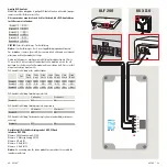
Connection (DIP switch 6 = off)
Switching
contact (N/O)
Supply
voltage
Central unit
1
2
3
4
5
6
AC/DC
AC/DC
Connection (DIP switch 6 = on)
automatic trip in the event of a supply voltage failure
Supply
voltage
Switching
contact (N/C)
”Closes when wind and/or rain“
”Opens when wind, rain and/or supply voltage failure“
+
−
A B C D E
1 2 3 4 5 6 7
8 9 10
A B C D E
1 2 3 4 5 6 7
8 9 10
ETHERNET
ETHERNET
RESET
RESET
USB
USB
A B C D E
1 2 3 4
5 6 7 8 9 10
A B C D E
1 2 3 4
5 6 7 8 9 10
ETHERNET
ETHERNET
RESET
RESET
USB
USB
KLF 200
KUX 110


