background image

4

THE OUTLAW’S GUIDE TO THE SMS-1

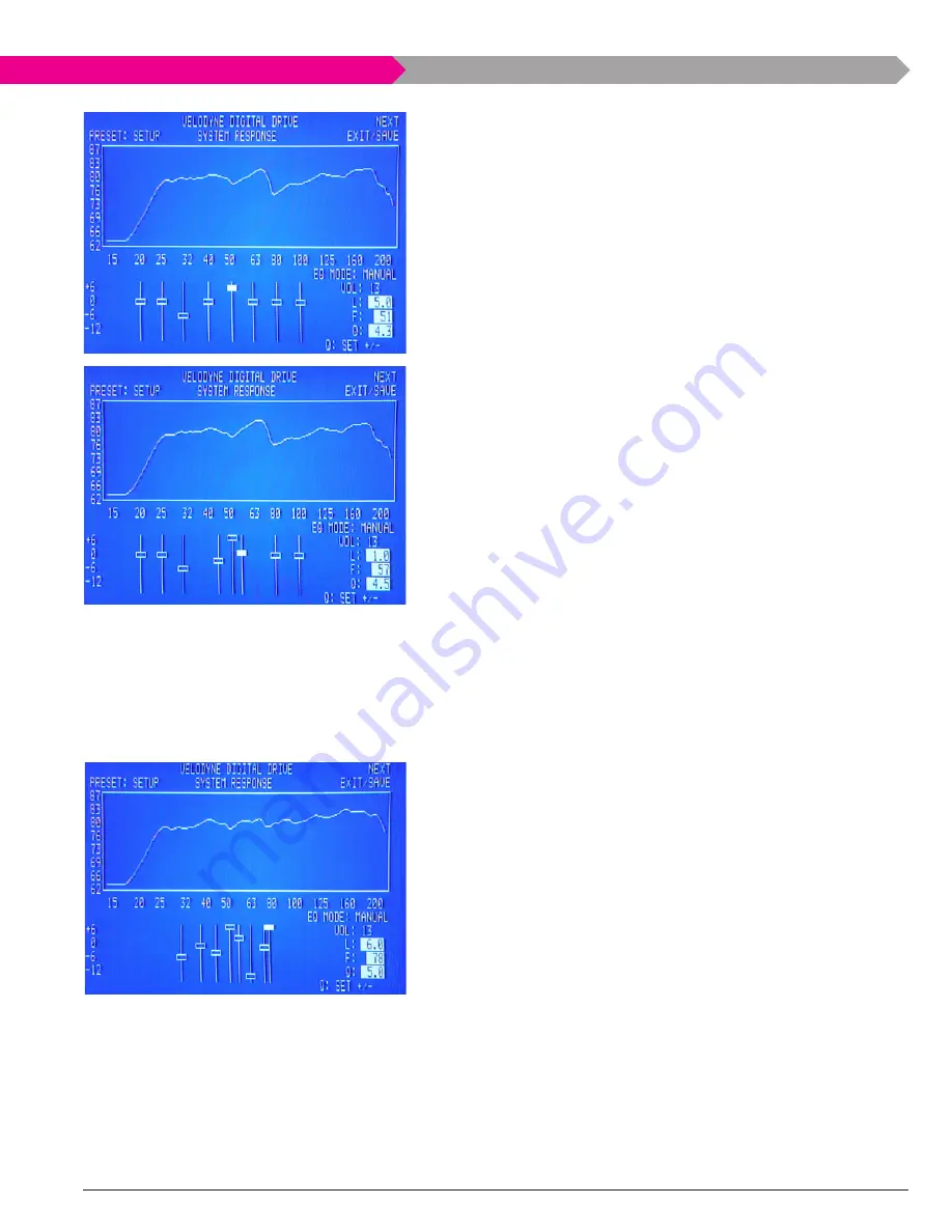
As is often the case, the first attempt isn’t an ideal solution to the system 
response problem.  We still have a dip.  A second pass at fixing it should 
start to involve multiple Eq channels.  In this case, we will use three chan-
nels, the fourth (40Hz), fifth (50Hz), and sixth (6Hz).  The fourth Eq will 
move from 40Hz to 45Hz, the level will be set to -.0db, and the q will be 
raised to 5.8.  The fifth Eq had already been adjusted somewhat, but will 
further move to 5Hz, have the level bumped up to 6.0db, and have the 
q of ..  The sixth Eq will move down to 57Hz with a q of 4.5 and a slight 
1.0db boost.  The System response curve below shows this second pass 
at fixing the 5Hz dip.  There’s still a bit of dip that ties into the neighbor-
ing peak, but we’ll address that as we continue with adjustments for that 
peak.
Once you have a feel for how to deal with a typical peak and a typical 
dip, you can simply work your way across the response curve.  Some 
care needs to be taken at areas where two dips interact (using the same 
reasoning applied to fixing individual dips without stacking Eq’s).  Like-
wise, some restraint is advisable near the lower limit of your subwoofer’s 
response.  If your subwoofer is rated down to 5Hz, then you should prob-
ably not try to apply 5db of boost at 0Hz – the “dip” in response there 
is most likely the natural response roll-off inherent in your subwoofer, 
and boosting it will just place undue burden on the sub at a frequency 
response range your subwoofer is intended to operate in.
Using the steps described above, we took the System response originally 
shown at the beginning of this example and transformed it into the Sys-
tem response shown below.  As you can tell, we ended up focusing our 
attention between 0Hz and 80Hz.  This is because the room response 
below 0Hz was already fairly even up to the point where the response 
of the example system’s LfM-1 subwoofer began to roll off.  Likewise, the 
crossover for the left and right speakers was set to 80Hz in our processor, 
so the subwoofer began tapering off at that point and passing responsi-
bility back to the mains (which the SMS-1 has no control over).
In the example above, we took some effort to keep the eight Eq’s laid out 
in their original order from left to right, but it is not necessary to do so.  
The SMS-1 will allow any Eq channel to be set to any frequency, regardless 
of where other channels are set.  This means that even though the first 
Eq channel defaults to 0Hz, it can be set to 10Hz.  The only drawback 
to doing this is the fact that the SMS-1 will continue to scroll through the 
eight Eq channels in their original order, so that if you have moved the 
first Eq to 75Hz (between the default positions for the sixth and seventh 
Eq’s) you would have to scroll all the way “down” past the fifth through 
second Eq channels to get to the first to make adjustments.  It will work 
just fine, but it can be very confusing if you have forgotten what order 
the Eq’s are in and are trying to make adjustments later.  bottom line: if 
your cursor seems to be skipping around between the Eq’s randomly, it is 
probably because the channels are no longer in their original order.

Summary of Contents for SMS-1 - OUTLAW GUIDE

Page 1: ...The Outlaw s Guide to the Subwoofer Management System SMS 1 Velodyne Digital Drive...

Page 2: ...uld still failtofit contactalicensedelectriciantoreplaceyourobsoleteoutlet Donotdefeatthesafetypurposeofthe polarized plug Power CordProtection Power supplycordsshouldberoutedsothattheyarenotlikelytob...

Page 3: ...ur main speakers The SMS 1 is capa ble of letting you adjust your subwoofer to compensate for the acoustical challenges created by the room around you flatten peaks lift nulls and generally smooth eve...

Page 4: ...tributors is particularly skilled with bullet points sort of a differ ent kind of gunslinger so we let him provide us with a handy feature list Your new Velodyne SMS 1 is a state of the art component...

Page 5: ...This may seem simple but the SMS 1 is a wily and resourceful piece of equipment that appears to be less than fond of the paparazzi We hope that the fourth contributor will be out of the hospital and...

Page 6: ...from view RP5 RS 232 Output This can be used to connect to other SMS 1 s if you have several units in your system RP6 RS 232 Input This can be used to connect to a PC for software updates a con trol s...

Page 7: ...ggers often found on receivers or sur round processors can be connected here to turn the SMS 1 on whenever a 12V signal is present The trigger must be enabled in the SMS 1 s menu We ll show you where...

Page 8: ...to accept with this button Reset Reset the unit to the last saved defaults including volume level and preset Menu Enter the setup mode menus This command must be accompanied by a series of numbers on...

Page 9: ...have the micro phone case open grab the wind screen and fit it over the end of the microphone 7 Plug the other end of the microphone cable into the SMS 1 s front input 8 Set the microphone in your pre...

Page 10: ...default screen press 3 2 1 on the remote This will start the automatic EQ process You ll see Self EQ in the bottom right hand corner of the SMS 1 s front panel display and you ll hear about 25 freque...

Page 11: ...balanced pre amp outputs you can use the bal anced LFE Input on the left side of the rear panel The SMS 1 is capable of using a mixture of balanced and unbalanced connections This means that you can...

Page 12: ...output carries the SMS 1 s test tones to your receiver or processor We recommend picking a spare video input on your receiver and leaving the SMS 1 connected but if you are running short on open input...

Page 13: ...located on the left side of the panel between the balanced inputs and the RS 232 ports An RS 232 port is not an uncommon sight on a surround processor or even on a receiver but on other components it...

Page 14: ...to reset the unit to the factory defaults or press 3 2 1 to start the Self EQ mode Setup Auto EQ Remember that cat we men tioned earlier We ve now decided it s best to be scared Those of you who went...

Page 15: ...nes and passes them directly to its subwoofer output There is a separate automatic EQ mode Auto EQ that is activated from the System Response screen by highlighting the EQ Mode setting and pressing SE...

Page 16: ...ll work just fine on a couch or chair Whatever stand you use take the dust cover out of the microphone case and slide it over the end of the microphone Once all of that is done put the microphone at y...

Page 17: ...ve Don t mind the dips and peaks in the curve we ll get to those shortly There are some slick tricks that you can do with the System Response screen covered in our Tips and Tricks section on page 27 a...

Page 18: ...ossover point The default crossover of 80Hz and the default slope of 24 dB octave happen to be the THX standard for a low pass crossover If you are using a receiver or processor that already provides...

Page 19: ...with those speakers in spite of its separate placement In general subwoofer phase switches are set by playing a test tone and using the switch position that gives the loudest output While limiting you...

Page 20: ...will want to highlight this setting and use the Set buttons on the remote to switch it to Active so that the SMS 1 uses its trigger If you don t have a trigger connected leave this Inactive There s a...

Page 21: ...to EQ process our interests currently are in manual EQ setup so we can leave it alone The heart of the System Response screen is the system response graph that takes up the top half of the screen This...

Page 22: ...equalizers close together and set the level to a positive value the equalizers Q values should be set as high as possible to limit interaction between the two equalizers Stacking is a one way street a...

Page 23: ...boost to both chan nels This sounds like a great way to pull a deep dip up to a level response Unfortunately it is also a great way to push a significantly boosted signal to the subwoofer Assume for...

Page 24: ...ge your subwoofer is intended to operate in Using the steps described above we took the System Response originally shown at the beginning of this example and transformed it into the Sys tem Response s...

Page 25: ...setting changes that you aren t happy with Want to start over again with a clean slate It is possible to easily reset the SMS 1 to the factory defaults To do this simply press the but tons 8 9 0 into...

Page 26: ...ussed are activated using special commands or strings of commands from the remote control Since it can be handy to have all of those commands gathered in a single place we have done just that below Ta...

Page 27: ...nd Q for each scenario you try is tedious and adjusting the settings to compare two options is too time consuming to let you get a good feel for how they compare To get around this you can change the...

Page 28: ...ld write an encyclopedia on acoustical treatment but we won t Likewise a great deal can be said about speaker placement but we are going to restrict ourselves to subwoofer placement because the SMS 1...

Page 29: ...eiver or processor while each sub s signal passed through a different SMS 1 The same system settings and EQ curve would be applied to both discrete subwoofer signals but those settings would yield an...

Page 30: ...al you may safely leave the SMS 1 turned on continuously with out any problems If you will be away from your system for an extended period of time Velodyne recommends unplugging the unit Troubleshooti...

Page 31: ...ecommended on page 17 and that receiver is not muted Test tone audible but no Microphone not connected Make certain microphone cable is connected at curve shown on display microphone and at SMS 1 Unit...

Page 32: ...32 THE OUTLAW S GUIDE TO THE SMS 1 WRITE EM IFYOU VE GOT EM NOTES...

Page 33: ...NOW YOU CAN PANIC...

Reviews: