background image

www.velodyneacoustics.com

User’s Manual

Deep Blue Series

5

REAR 


 PANEL


    CONNECTIONS


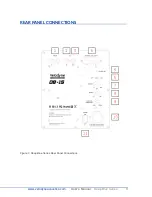
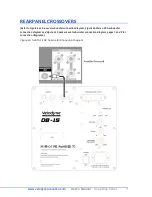
Figure 1. Deep Blue Series Rear Panel Connections

Summary of Contents for Deep Blue Series

Page 1: ...USER S MANUAL Deep Blue Series DB 8 DB 10 DB 12 DB 15...

Page 2: ...e Acoustics subwoofer Our passion for high performance low distortion bass is the driving force behind our worldwide reputation in audio and technical innovation We are pleased to bring the Velodyne A...

Page 3: ...oduct may be equipped with a polarized alternating current line plug a plug having one blade wider than the other This plug will fit into the power outlet only one way This is a safety feature If you...

Page 4: ...es ii TABLE OF CONTENTS Congratulations 1 Installation 2 Rear Panel Connections 5 Crossovers 7 Interconnect Cables 9 Care of Your Subwoofer 9 Protection Circuitry 9 Troubleshooting and Service 10 Spec...

Page 5: ...n Be sure to unpack the system carefully to avoid damage This unit is heavy so use caution when lifting or moving to avoid injury Save the carton and all packaging materials for future use Packing thi...

Page 6: ...Acoustics subwoofer it must remain in an upright position Placing shipping or storing your subwoofer in any other position for an extended period of time may result in damage to the unit This type of...

Page 7: ...rmation might be present in each channel going to your main speakers If using with audio equipment with LFE OUT set speaker to large and indicate no subwoofer is present Important Do not use both LINE...

Page 8: ...LFE that is internally filtered settable at the receiver processor and designed to be used with a powered subwoofer In some installations it may be beneficial to use BOTH the Velodyne Acoustics cross...

Page 9: ...www velodyneacoustics com User s Manual Deep Blue Series 5 REAR PANEL CONNECTIONS Figure 1 Deep Blue Series Rear Panel Connections...

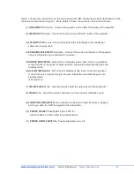
Page 10: ...minals of your amplifier or receiver 5 POWER INDICATOR Red Unit is in standby mode blue Unit is in operation mode If there is no signal for eight minutes subwoofer automatically goes into standby mode...

Page 11: ...NEL CROSSOVERS Refer to Figure 2a Line Levelsubwooferconnectiondiagram Figure 2b Stereo RCAsubwoofer connection diagram and Figure 2c Speaker Level subwoofer connection diagram pages 7 and 8 for conne...

Page 12: ...www velodyneacoustics com User s Manual Deep Blue Series 8 Figure 2b Speaker Level Subwoofer Connection Diagram...

Page 13: ...www velodyneacoustics com User s Manual Deep Blue Series 9 9 Figure 2c Speaker Level Subwoofer Connection Diagram...

Page 14: ...appearance purposes is all that is required We suggest you avoid any harsh detergents or chemicals when cleaning the cabinet The finish on the cabinet may become damaged with the use of abrasives det...

Page 15: ...res are fully inserted into the spring clip connectors and that no wires are touching from one terminal to another If the protection circuitry is active the unit may cycle on and off until operating p...

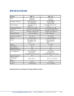
Page 16: ...e Dual Ferrite Motor Dual Ferrite Motor Low Pass Crossover 50 200 Hz 50 200 Hz Outputs LFE pass through LFE pass through Inputs RCA Line Level LFE and Speaker Level inputs RCA Line Level LFE and Speak...

Page 17: ...Dual Ferrite Motor Dual Ferrite Motor Low Pass Crossover 50 200 Hz 50 200 Hz Outputs LFE pass through LFE pass through Inputs RCA Line Level LFE and Speaker Level inputs RCA Line Level LFE and Speaker...

Page 18: ...your product you will still need to submit to Velodyne Acoustics the original sales invoice or other proof of ownership and date of purchase Velodyne Acoustics GmbH Alsterkrugchausse 435 22335 Hamburg...

Reviews: