74
110332-02 - 6/22
PHTM II
Installation, Operating & Service Instructions
18
Troubleshooting
(continued)
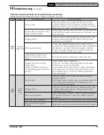
D. Troubleshooting with Active Fault Code.
Control uses following codes to describe abnormal operation:
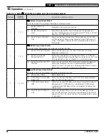
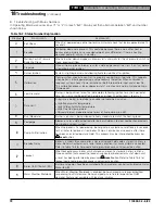
Table 18-4: Lockout/Hold/Warning Symbol Description
Code
Type
Boiler Status
Description
E
Lockout
Shutdown
When a lockout occurs, boiler will shut down and event is stored in
history,
b
, menu. Once condition that caused lockout is corrected,
boiler remains shut down until a reset has been performed by pressing
!
reset
button.
H
Hold
Shutdown
When a hold occurs, boiler will shut down. Event is stored in history,
b
,
menu. Boiler will automatically restart once condition that caused hold is
corrected.
Warning
Free to operate
When a warning occurs, an abnormal condition has affected boiler
operation and event is stored in history,
b
, menu. Boiler continues to
operate.
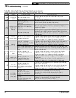
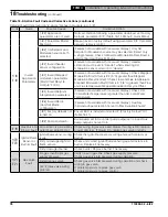
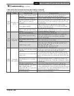
Table 18-5: Active Fault Code and Corrective Actions
Detailed Fault Code found on "
b
" and "
c
" menus in brackets, e.g. [
1
.
0
].
Code
Name
Possible Cause
Corrective Action
H01
Anti-Short
Cycle
[
1
.
0
] While thermostat demand
present, boiler has cycled off too
quickly and restart is delayed.
Boiler will restart automatically after the minimum off
time (Anti-Short Cycle Time).
[
1
.
1
] Urgent calibration cooling delay.
Urgent calibration demand present,
waiting for supply temperature to
decrease.
Boiler will start after supply temperature drops below
95°F (35°C). Low supply temperature helps to ensure
a successful calibration. No action is necessary.
[
1
.
2
] Flow switch closed before boiler
pump on. Boiler start delayed waiting
for flow switch to open.
Boiler pump will start after flow switch open state is
proven. Maximum waiting time is 30 s, otherwise
E5
.
4
is set. Check for flow switch or piping issue.
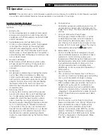
H02
Safety
Limit
Open
External limit is open.
If water temperature too high see
H04
/
E04
for
corrective action.
• Check external limit setting, verify limit setting.
• Check external limit wiring.
• If external limit is not used, check jumper is installed
according to wiring diagram.
Optional LWCO, low water condition.
Check LWCO indications, if yellow light "On":
• Verify that system is full of water and all air has been
properly purged from system.
• Check system air vent is unobstructed and properly
functioning, a blocked air vent can result in low water
condition.
If yellow and green light "Off", check LWCO wiring
harness.
Loose wire.
If external limit is not used, check jumper is installed
according to wiring diagram.
Thermal fuse is open.
Check thermal fuse for continuity. If "open" consult
manufacturer.

