28
Series 49
Installation, Operating & Service Instructions
111368-04 - 1/22
9
Electrical
(continued)
Figur
e 9-4:
L
ad
der Dia
gr
am 49-350S thr
ough 49-550S,
NON CSD-1
Page 1: ...trical 24 10 System Start Up and Checkout 31 11 Operation 39 12 Before Leaving Jobsite 40 13 Service and Maintenance 41 14 How it Works 45 15 Troubleshooting 49 16 Service Parts 56 Appendix A Steam Bo...
Page 2: ...at if not avoided could result in death or serious injury Important Definitions of Warnings DANGER Explosion Hazard DO NOT store or use gasoline or other flammable vapors or liquids in the vicinity of...
Page 3: ...tect you from a release of hot water or steam Do not rely solely on boiler temperature and pressure gauge when making this judgement Install all guards cover plates and enclosures before leaving boile...
Page 4: ...er may leak water or steam at the end of its useful life Be sure to protect walls carpets and valuables from water or steam that could leak from boiler WARNING Asphyxiation Hazard Fire Hazard A qualif...
Page 5: ...517 124 82 0 49 250S 250 206 646 155 82 0 49 299S 299 246 771 185 82 0 49 350S 350 284 890 213 81 0 82 5 49 399S 399 323 1012 242 81 0 82 5 49 450S 450 365 1143 274 81 0 82 5 49 500S 500 405 1269 304...
Page 6: ...1 21 3 8 30 1 2 2 6 1 2 3 4 103 49 150S 4 41 21 3 8 30 1 2 2 6 1 2 3 4 124 49 175S 5 41 26 7 16 30 2 2 2 7 3 4 3 4 144 49 200S 5 41 26 7 16 30 2 2 2 7 3 4 3 4 165 49 250S 6 41 31 1 2 30 2 2 2 8 3 4 3...
Page 7: ...6 1 2 11 49 175S 26 7 16 10 3 16 7 7 13 1 2 49 200S 26 7 16 10 3 16 7 7 13 1 2 49 250S 31 1 2 15 1 4 8 8 16 49 299S 36 9 16 20 3 8 8 8 18 1 2 Left Side Right Side Front 6 1 2 A 8 Ref E 8 B 5 3 8 2 Ri...
Page 8: ...S 61 7 8 15 1 4 15 1 4 15 1 4 16 27 1 2 8 8 Left Side Right Side Front 6 1 2 A 8 Ref 8 B C D 5 3 8 2 Riser All sizes 3 1 2 26 20 16 1 2 26 5 8 NWL BVS Gauge Glass Auto Reset Pressure Limit Gas Line Op...
Page 9: ...Bushed Down for Drain C 2 Skimming Connection or Bushed Down for Auto Reset Pressure Limit Manual Reset Pressure Limit and Pressure Gauge D 1 2 Gauge Glass E 3 4 Auto Reset LWCO F 1 Relief Valve G 3 4...
Page 10: ...y combustible materials gasoline or other flammable liquids from area around boiler 8 Check for and remove any potential combustion air contaminants from area around boiler See Table 4 1 Clearances 1...
Page 11: ...ended from left side right side and front 4 Locating Boiler continued Figure 4 2 Minimum Alcove Clearances 49 075S through 49 299S Boiler A 49 075S 16 5 16 49 100S 16 5 16 49 125S 21 3 8 49 150S 21 3...
Page 12: ...continued Figure 4 3 Minimum Alcove Clearances 49 350S through 49 550S Boiler A 49 350S 41 5 8 49 399S 46 11 16 49 450S 51 3 4 49 500S 56 13 16 49 550S 61 7 8 NOTICE 24 in service clearance recommende...
Page 13: ...t fans such as range hoods and bathroom exhausts so they will operate at maxi mum speed Do not operate a summer exhaust fan Close fireplace dampers Before Removing Existing Boiler Take pictures and me...
Page 14: ...miscellaneous parts carton from outer shipping carton Unpack Boiler Figure 5 1 Packaged 49 100S through 49 250S DANGER Use precautions and appropriate rigging apparatus when moving heavy objects Reli...
Page 15: ...n fireplace or other solid fuel appliance 5 Prior to boiler installation inspect chimney for obstructions or other defects and correct as required Clean chimney as necessary 6 The vertical section of...
Page 16: ...nd Black BVS FRS quick connects to BVS Wires are interchangeable 4 Install vent piping A See Figure 3 4 for vent sizes and locations See Figure 4 2 for clearances B Install vent piping from vent dampe...
Page 17: ...es and locations See Figure 4 3 for clearances B Install vent piping from vent damper outlets to chimney See Figure 6 6 for typical vent installation WARNING This installation is not complete until re...
Page 18: ...This applies even if existing boiler has one of the piping mistakes shown in Figure 7 1 and appears to be working If two or more steam mains must be connected to boiler connect a separate take off for...
Page 19: ...llation Operating Service Instructions 7 Steam Piping continued Figure 7 1 Common Near Boiler Piping Mistakes WRONG Take off between risers WRONG Header bullheaded into take off and equalizer WRONG Ta...
Page 20: ...on boiler right side using nipple and elbow supplied See Figures 3 4 and 3 5 3 6 and Table 3 7 DANGER Pipe relief valve discharge to a safe location Do not install any valves between boiler and relief...
Page 21: ...2 2 2 2 D 1 1 4 1 1 2 1 1 2 1 1 2 1 3 2 indicates three 2 inch risers 7 Steam Piping continued A B A A B Supply Main to be taken off top of header vertically Boiler Fill Gate Valve Steam wet return pi...
Page 22: ...tant to action of liquefied petroleum gas D Install sediment trap ground joint union and manual shut off valve upstream of combination gas valve within 6 ft of boiler See Figure 8 2 E All above ground...
Page 23: ...alve 8 Gas Piping continued Figure 8 4 49 350S through 49 550S Gas Manifold and Control Assembly Dual Combination Gas Valves Combination Gas Valve Pilot Tubing Manifold Assembly Ignitor Sensor Pilot B...
Page 24: ...after installation DANGER Electrical Shock Hazard Disconnect electrical supply before installing or performing maintenance Electrical power may be supplied from more than one circuit Lock out all elec...
Page 25: ...25 111368 04 1 22 Series 49 Installation Operating Service Instructions 9 Electrical continued Figure 9 1 Wiring Diagram 49 075S through 49 299S...
Page 26: ...26 Series 49 Installation Operating Service Instructions 111368 04 1 22 9 Electrical continued Figure 9 2 Ladder Diagram 49 075S through 49 299S...
Page 27: ...27 111368 04 1 22 Series 49 Installation Operating Service Instructions 9 Electrical continued Figure 9 3 Wiring Diagram 49 350S through 49 550S Non CSD 1...
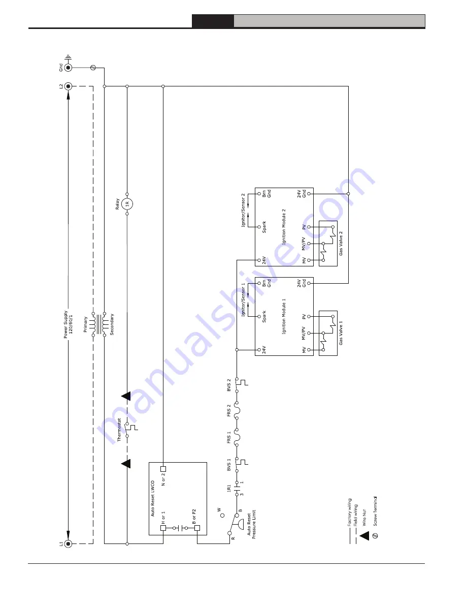
Page 28: ...28 Series 49 Installation Operating Service Instructions 111368 04 1 22 9 Electrical continued Figure 9 4 Ladder Diagram 49 350S through 49 550S NON CSD 1...
Page 29: ...29 111368 04 1 22 Series 49 Installation Operating Service Instructions 9 Electrical continued Figure 9 5 Wiring Diagram 49 450S through 49 550S CSD 1...
Page 30: ...24V Gnd Ignition Module 1 Alarm 2 Alarm 1 Ignition Module 2 Alarm 2 Alarm 1 Gas Valve 1 Gas Valve 2 B or P2 H or 1 N or 2 Auto Reset LWCO H or 1 N or 2 B or P2 C or P1 Manual Reset LWCO L1 L2 Gnd Pow...
Page 31: ...ilot flame signal must be 1 A microampere DC direct current For reliable operation flame signal should be 2 A or greater Flame current can be determined by flashing green STATUS LED on ignition module...
Page 32: ...32 Series 49 Installation Operating Service Instructions 111368 04 1 22 10 System Start Up and Checkout continued Figure 10 1 Operating Instructions...
Page 33: ...10 System Start Up and Checkout continued Figure 10 3 Pilot Burner Flame Top Panels Rear Panel Step 1 Up Step 2 Forward Step 3 Down Lower Front Tie Bar Front Removable Door Figure 10 2 Front Door Remo...
Page 34: ...seconds control returns to normal sequence If flame out of sequence remains longer than 10 seconds control will resume normal operation 1 hour after error is corrected Check for pilot flame Replace g...
Page 35: ...System Start Up and Checkout continued Figure 10 5 Main Burner Flame Incandescent Outer Mantle Blue with occasional orange flashing Outer Cone Darker transparent blue Inner Cone Sharply outlined with...
Page 36: ...peration while boiler is running Slowly open drain valve and drain boiler until water level drops below auto reset LWCO line Water should be visible in gauge glass when auto reset LWCO shuts down both...
Page 37: ...37 111368 04 1 22 Series 49 Installation Operating Service Instructions 10 System Start Up and Checkout continued Figure 10 6 Combination Gas Valve Detail...
Page 38: ...e from shutoff valve to combination gas valve s Add 5 cubic inches for each combination gas valve 2 Determine test time per Figure 10 7 3 Turn off gas to boiler 4 Install pressure tap on combination g...
Page 39: ...pplied across MV and MV PV terminals opening valve and establishing main burner flame Control Operation LWCO Interrupts burner operation when water in boiler drops below cut off level Power is restore...
Page 40: ...flame Checked main burner flames Checked gas input rate Checked gas inlet pressure Checked gas manifold pressure Checked vent damper operation Performed combination gas valve shutdown test Tested aut...
Page 41: ...clothing that is sufficiently tight around potential entry points for RCF dust 3 Gloves 4 Eye protection such as goggles safety glasses with side shields or full facepiece Take steps to assure adequa...
Page 42: ...d chimney Inspect masonry chimney liner Repair or replace defects and or deterioration B If masonry chimney is lined verify lining is in good condition and there are no openings into chimney C Remove...
Page 43: ...iping A Check all system piping for leaks B Repair any leaks before placing back into service 6 Inspect Pressure Gauge A Needle should move with variation in pressure B Replace gauge if needed 7 Opera...
Page 44: ...49 299S 0 02 0 21 49 350S 0 02 0 23 49 399S 0 02 0 25 49 450S 0 02 0 27 49 500S 0 02 0 29 49 550S 0 03 0 31 Based on maximum leak rate of 2 steamable water per month NOTICE When substantial amount of...
Page 45: ...vel is returned to normal 6 Flame Rollout Switch FRS If flames roll out of burner tubes switch will open requiring replacement and cause burners to shut down If switch trips determine cause of flame r...
Page 46: ...46 Series 49 Installation Operating Service Instructions 111368 04 1 22 14 How It Works continued Figure 14 1 Controls Location 49 075S through 49 299S 8 7 6 11 1 2 9 4 5 10 3...
Page 47: ...47 111368 04 1 22 Series 49 Installation Operating Service Instructions Figure 14 2 Controls Location 49 350S through 49 550S Non CSD 1 14 How It Works continued 7 8 7 8 6 6 1 2 11 1 4 5 10 4 3 3...
Page 48: ...48 Series 49 Installation Operating Service Instructions 111368 04 1 22 Figure 14 3 Controls Location 49 450S through 49 550S CSD 1 14 How It Works continued 7 8 7 8 6 6 1 2 11 1 5 10 4 14 12 13 3 3 4...
Page 49: ...rical meter and gas pressure gauge available for use 3 Check electrical connections on boiler before proceeding See Figures 9 1 9 3 or 9 5 A Ensure 120VAC power polarity is correct and boiler is prope...
Page 50: ...50 Series 49 Installation Operating Service Instructions 111368 04 1 22 15Troubleshooting continued Figure 15 1 Troubleshooting Flow Diagram 49 075S through 49 299S...
Page 51: ...51 111368 04 1 22 Series 49 Installation Operating Service Instructions 15Troubleshooting continued Figure 15 1 Troubleshooting Flow Diagram 49 075S through 49 299S continued from previous page...
Page 52: ...52 Series 49 Installation Operating Service Instructions 111368 04 1 22 15Troubleshooting continued Figure 15 2 Troubleshooting Flow Diagram 49 350S through 49 550S Non CSD 1...
Page 53: ...111368 04 1 22 Series 49 Installation Operating Service Instructions 15Troubleshooting continued Figure 15 2 Troubleshooting Flow Diagram 49 350S through 49 550S Non CSD 1 continued from previous pag...
Page 54: ...54 Series 49 Installation Operating Service Instructions 111368 04 1 22 15Troubleshooting continued Figure 15 3 Troubleshooting Flow Diagram 49 450S through 49 550S CSD 1...
Page 55: ...55 111368 04 1 22 Series 49 Installation Operating Service Instructions Figure 15 3 Troubleshooting Flow Diagram 49 450S through 49 550S CSD 1 continued from previous page 15Troubleshooting continued...
Page 56: ...d through your local Velocity Boiler Works wholesale distributor Should you require assistance in locating a Velocity Boiler Works distributor in your area or you have questions regarding the availabi...
Page 57: ...Assembly includes both canopy and base gaskets 111268 03 1 111268 03 1 111268 04 1 111268 04 1 111268 05 1 111268 05 1 111268 06 1 111268 07 1 1B Baffles set of 3 111263 01 1 111263 01 2 1C Canopy Gas...
Page 58: ...58 Series 49 Installation Operating Service Instructions 111368 04 1 22 16 Service Parts continued 2A 2B 2C 2D 2E 2G 2H 2F...
Page 59: ...D Canopy Gasket 6206001 2 2E Left Side Canopy 111290 04 1 111290 04 1 111290 05 1 111290 06 1 111290 06 1 2F Right Side Canopy 111290 05 1 111290 06 1 111290 06 1 111290 06 1 111290 07 1 2G Left Side...
Page 60: ...Part Number Quantity 49 075S 49 100S 49 125S 49 150S 49 175S 49 200S 49 250S 49 299S 3A Complete Base Assembly Base Gasket included Consult Factory 110901 03 1 110902 04 1 110901 04 1 110902 05 1 110...
Page 61: ...00S 49 550S 4A Complete Left Half Base Assembly 110908 04 1 110908 04 1 111236 05 1 111236 06 1 111236 06 1 4B Complete Right Half Base Assembly 110909 04 1 110909 05 1 111237 05 1 111237 05 1 111237...
Page 62: ...1 5C Pilot 111279 01 1 5D 1 4 Pilot Tubing 109611 01 1 Key No Description Part Number Quantity 49 350S 49 399S 49 450S 49 500S 49 550S 5A Left Manifold Burners Pilot Insulation Assembly 111277 04 1 1...
Page 63: ...Instructions 16 Service Parts continued 6A 6A Key No Description Part Number Quantity 49 075S 49 100S 49 125S 49 150S 49 175S 49 200S 49 250S 49 299S 6A Jacket Set 111365 03 1 111365 03 1 111365 04 1...
Page 64: ...ce Parts continued 7A 7A 7B 7B Key No Description Part Number Quantity 49 350S 49 399S 49 450S 49 500S 49 550S 7A Left Side Jacket Set 111370 04 1 111370 04 1 111370 05 1 111370 06 1 111370 06 1 7B Ri...
Page 65: ...200S 49 250S 49 299S 8A Non CSD 1 Ignition Module Honeywell 109633 01 1 8B Transformer 106034 01 1 8C Relay 111282 01 1 Key No Description Part Number Quantity 49 350S 49 399S 49 450S 49 500S 49 550S...
Page 66: ...34 03 1 109634 04 1 109634 04 1 109634 05 1 109634 05 1 9B Pressure Gauge 109707 01 1 9C Gauge Glass 111271 01 1 9D Relief Valve 111267 01 1 9E Pressure Limit Auto Reset Honeywell 111280 01 1 9F Press...
Page 67: ...Glass 111271 01 1 9D Relief Valve 111267 01 1 111304 01 1 9E Pressure Limit Auto Reset Honeywell 111280 01 1 9F CSD 1 Pressure Limit Manual Reset Honeywell N A 111281 01 1 9G LWCO Auto Reset M M 1112...
Page 68: ...68 Series 49 Installation Operating Service Instructions 111368 04 1 22 16 Service Parts continued 10B 10C 10D 10E 10A...
Page 69: ...200S 49 250S 49 299S 10A Main Harness Power Harness 111264 01 1 10B Pilot Ground Wire 111278 01 1 10C Ignition Cable 111274 01 1 Key No Description Part Number Quantity 49 350S 49 399S 49 450S 49 500...
Page 70: ...73 01 1 Not Shown Pressure Limit Manual Reset Honeywell 111281 01 1 Key No Description Part Number Quantity 49 350S 49 399S 49 450S 49 500S 49 550S Not Shown Hydrolevel CSD 1 Kit 111293 01 1 N A Not S...
Page 71: ...This valve is a just in case valve You will not close this after the skimming process starts This pipe nipple must be horizontal and must come straight out It can not elbow up We are trying to skim th...
Page 72: ...their functions are as follows 1 Circulator Mount circulator as shown in Figure B 1 Circulator should be located as low and as close to boiler as practical Do not install valves or other devices havin...
Page 73: ...A call for heat from the IWH thermostat will energize relay making both sets of contacts One contact energizes the circulator Other contact will make boiler T T circuit firing burners If boiler water...
Page 74: ...1 Wire blue lead to terminal 5 and gray white lead to terminal 6 in 150S MD See Electrical Section for complete boiler wiring diagram Figure C 2 Auto Reset LWCO Connector in Boiler Wiring Harness 150S...
Page 75: ...75 111368 04 1 22 Series 49 Installation Operating Service Instructions SERVICE RECORD SERVICE PERFORMED DATE...
Page 76: ...76 Series 49 Installation Operating Service Instructions 111368 04 1 22 Velocity Boiler Works LLC P O Box 14818 3633 I Street Philadelphia PA 19134...