background image

PCS10 - K8047 recorder  / Logger

14

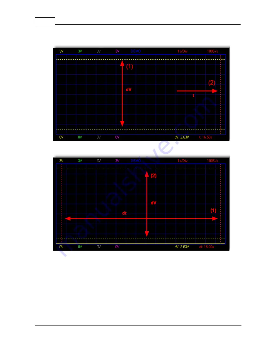
1.5.4.2

Markers dV & t

1.5.4.3

Markers V & dt

.

1.5.4.4

Move the markers

Place the mouse pointer over a dached marker line.

Press and hold the left mouse button.

The marker line turns solid.

Drag the marker to the approriate position.

Summary of Contents for PCS10

Page 1: ...User manual 4 CHANNEL USB RECORDER LOGGER PCS10 K8047...

Page 2: ...ronics proceed at breakneck speed we have always been able to create the ideal mix between innovation and durability The innovations are mainly expressed in our scopes which are created with the aid o...

Page 3: ...els 8 Time div 8 Measuring 9 Scrollbar 9 Digital readout 9 Momentary voltage 10 Max Min voltage storage 10 5 Menu options 10 File menu 11 Date 12 Edit menu 12 Options menu 13 Colors 13 View menu 13 Ma...

Page 4: ...17 Spooling 17 USB Index 18 PCS10 K8047 recorder Logger II...

Page 5: ...s recording Minimum maximum sample hold function for DVM From 1 sec to 1000 sec per division Storage and recall of screens full colour or data Automatic recording option for long time recordings On sc...

Page 6: ...ase invoice VELLEMAN Components limits its responsibility to the reparation of defects or as VELLEMAN Components deems necessary to the replacement or reparation of defective components Costs and risk...

Page 7: ...s correctly connected with the computer 1 2 2 diagnostic led Lights when the unit is recording data 1 2 3 Signal input 4 input channels enable you to measure 4 signals at the same time 1 2 4 USB outpu...

Page 8: ...s 1 3 1 Analog screen K8047 PCS10 screenshot Using this screen the 4 channels can be viewed simultanously as a trace on the screen 1 3 2 Digital screen K8047 PCS10 screenshot Powerfull feature which a...

Page 9: ...English 7 PCS10 K8047 2003 Velleman Components 1 4 Software controls 1 4 1 Analog readout 1 4 1 1 Voltage range 1 4 1 2 Channels...

Page 10: ...PCS10 K8047 recorder Logger 8 1 4 1 3 Time div 1 4 1 4 Measuring...

Page 11: ...English 9 PCS10 K8047 2003 Velleman Components 1 4 1 5 Scrollbar 1 4 2 Digital readout 1 4 2 1 Momentary voltage...

Page 12: ...1 5 Menu options 1 5 1 File menu Open image Opens a image file and display it on the screen Open data Opens and displays the waveform data saved in text format using the Save data option Save image Sa...

Page 13: ...step Timescale setting 100 samples 1second Voltage range CH1 Voltage range channel 1 measured value 255 corresponds to 15V CH2 Voltage range channel 2 measured value 255 corresponds to 30V CH3 Voltage...

Page 14: ...he waveform display To change the color of an item click the corresponding button This will open a dialog in which you can select a new color Full color selection is possible only if True color 24bit...

Page 15: ...fference between the two markers is displayed 1 Two horizontal markers for measuring voltage 2 You can move the markers by using your mouse DVM display Displays the digital screen recorder logger Brig...

Page 16: ...14 1 5 4 2 Markers dV t 1 5 4 3 Markers V dt 1 5 4 4 Move the markers Place the mouse pointer over a dached marker line Press and hold the left mouse button The marker line turns solid Drag the marker...

Page 17: ...ts 1 5 4 5 Display digital K8047 PCS10 screenshot Unique feature allowing digital visualization of the max and min voltage peak during measurements 1 5 5 Help menu Contents Display the help file About...

Page 18: ...e http www velleman be 1 7 glossary 1 7 1 Administrator A person responsible for setting up and managing domain controllers or local computers and their user and group accounts assigning passwords and...

Page 19: ...nt to a printer by the user and then stores it on disk or in memory until the printer is ready for it This collection of dynamic link libraries DLLs receives processes schedules and distributes docume...

Page 20: ...E mail 16 Exit 10 F File menu 10 full coulour 10 Full measurement range 7 H Hardware 3 Help menu 15 I Input channels 4 input ranges 3 Input resistance 3 M markers 6 Markers dV t 13 Markers V dt 13 Max...

Page 21: ...put 4 Single 8 Software 3 Software updates 3 Specifications 3 System requirements 3 T time difference 13 time setting 8 Time div 8 Troubleshooting 16 True color 12 U USB output 4 USB power indication...

Page 22: ...Velleman Instruments is a division of Velleman Components NV Legen Heirweg 33 9890 Gavere Belgium Internet site http www velleman be E mail support velleman be Velleman Instruments 2003_UK...

Reviews: