


5
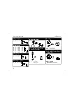
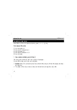
R1 : 10K (1 - 0 - 3 - B)
R2 : 10K (1 - 0 - 3 - B)
R3 : 1K (1 - 0 - 2 - B)
R4 : 10K (1 - 0 - 3 - B)
R5 : 4K7 (4 - 7 - 2 - B)
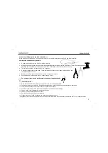
2. Resistors
R...
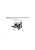
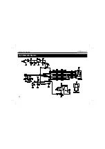
Construction main PCB
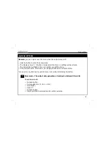
D1 : 1N4007
D2 : 1N4007
D...
CATHODE
IC1 : 14P
3. IC socket, Watch the
position of the notch!
1. Diodes. Watch the polarity!
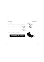
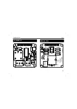
(1) Main PCB
2
1
g
f e
d
b a
+5
V
gnd
SET
NO COM NC
+ -
12VDC
V
e
lle
m
an P
8082'1
24V
/3
A
ma
x
.
C4
C3
R5
R4
R3
R2
R1
C7
C1
C2
C5
C6
D1
D2
IC1
RY
1
SK1
SK4
SW
1
T1
VR1
1
C1
C2
COM
NO
NC
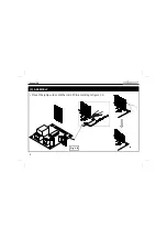
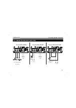
Break the PCB into two pieces.
2
1
g
f
ed
b
a
+5V
gnd
SE
T
NO CO
M
N
C
+ -
12V
D
C
Velleman P8082'1
24V/3A
max.
C4
C3
R5
R4
R3
R2
R1
C7
C1
C2
C5
C6
D1
D2
IC
1
RY1
SK
1
SK4
SW1
T1
VR
1
1
C1
C2
CO
M
NO
NC
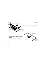
Setup:
Velleman
: 1m. timer/1
o: 1m. timer/0
d: default
S: set code
c: cont.
t: timer
cw cc
w
0
cw
1
cc
w
0
cw
1
co
d
e
:
def
a
u
lt
f
.
g
e
d
c
b
a
en
c
2
en
c
1
+5
V
21
.
g
f
e
d
c
b
a
+5V
gnd
P
8082'
1
R1
3
R1
2
R1
1
R1
0
R9
R8
R7
R6
DY1
SW
2
1
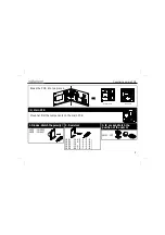
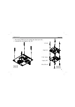
Display PCB
Main PCB
Mount at first the components on the main PCB