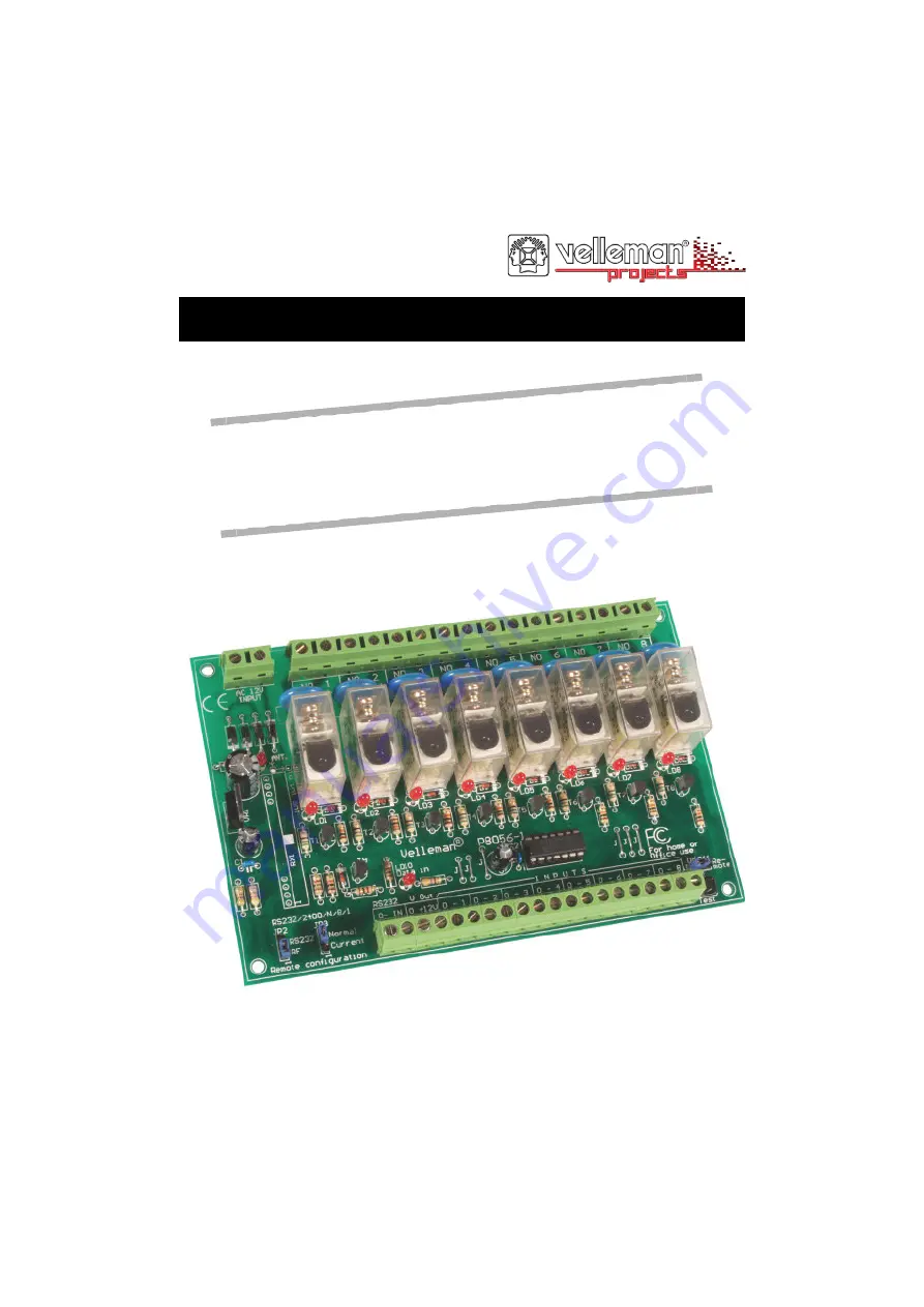
Eight channel remote relay card
ILLUSTRATED ASSEMBLY MANUAL
H8056IP-1
This relay c
ard can be
used in sev
eral ways :
stand
alone card,
addressed
by switche
s or open c
ollector
outputs or
remote con
trolled thro
ugh RS232
.
K8056
Page 1: ...l remote relay card ILLUSTRATED ASSEMBLY MANUAL H8056IP 1 This relay card can be used in several ways stand alone card addressed by switches or open collector outputs or remote controlled through RS232 K8056 K8056 ...
Page 2: ... may write custom applications in any language you want or on any platform you want Test software can be downloaded from our web site This device complies with Part 15 of the FCC Rules provided the enclosed instructions are followed to the letter Use of the device is subject to the following conditions 1 this device must not cause harmful interference and 2 the operation of this device should not ...
Page 3: ...10K or 1K Optional RF driving possibility using RX433 type module Together with K8058 eight channel RF remote control Specifications Power 12Vac 500mA including 12V output Unregulated 12Vdc 200mA power output Diagnostic test software Separate relay on off test with moment or toggle function Clear all set all relays function Address selection up to 255 cards can be selected Emergency stop for all c...
Page 4: ...agonal cutter to trim excess wires To avoid injury when cutting excess leads hold the lead so they cannot fly towards the eyes Needle nose pliers for bending leads or to hold compo nents in place Small blade and Phillips screwdrivers A basic range is fine For some projects a basic multi meter is required or might be handy 1 2 Assembly Hints Make sure the skill level matches your experience to avoi...
Page 5: ... manual updates indicated as NOTE on a separate leaflet 1 3 Soldering Hints 1 Mount the component against the PCB sur face and carefully solder the leads 2 Make sure the solder joints are cone shaped and shiny 3 Trim excess leads as close as possible to the solder joint REMOVE THEM FROM THE TAPE ONE AT A TIME Assembly hints AXIAL COMPONENTS ARE TAPED IN THE CORRECT MOUNTING SEQUENCE ...
Page 6: ...5V1 3 Zener diode check the polarity CATHODE ZD R8 56 5 6 0 B R9 10K 1 0 3 B R10 56 5 6 0 B R11 10K 1 0 3 B R12 56 5 6 0 B R13 56 5 6 0 B R14 56 5 6 0 B R15 10K 1 0 3 B R16 10K 1 0 3 B R17 10K 1 0 3 B R18 1K 1 0 2 B R19 470 4 7 1 B R20 4R7 4 7 B B R21 4R7 4 7 B B R22 1K 1 0 2 B R23 10K 1 0 3 B R24 1K 1 0 2 B D1 1N4007 D2 1N4007 D3 1N4007 D4 1N4007 5 Diodes check the polarity CATHODE D SW1 Test KRS...
Page 7: ...7 LD8 LD9 LD10 3mm RED T1 T2 T3 T4 T5 BC547B T6 T7 T8 T9 10 Transistors T1 JP1 3p ON OFF remote JP2 3p RS232 RF JP3 3p Normal Current 11 Header C3 100µF C4 100µF 12 Electrolytic capacitors Watch the polarity C ATTENTION SK2 to SK9 are 7 5mm pitch connectors SK12 to SK19 are 5mm pitch connectors SK1 2p AC 12V input SK2 2p SK3 2p SK4 2p SK5 2p SK6 2p Output 1 8 SK7 2p SK8 2p SK9 2p 13 Screw connecto...
Page 8: ...nput 1 8 VDR1 VDR2 VDR3 VDR4 VDR5 VDR6 VDR7 VDR8 14 VDR s VDR300 300VAC 385VDC VR1 UA7805 Check the orientation 15 Voltage regulator VR C5 1000µF 16 Electrolytic capacitor Watch the polarity C RY1 RY2 RY3 RY4 VR10V121C RY5 RY6 RY7 RY8 17 Relays IC1 VK8056 programmed Pic16F630 or eq 18 IC Watch the position of the notch ...
Page 9: ...current loop long cable select current The impedance will be 1Kohm 2 Wireless link It is possible to use the K8056 together with a remote control e g our K8058 In this case an optional receiver module type RX433 is available The receiver module is mounted on the left hand side of the K8056 board Watch the position the coil point to the relays of the K8056 If you choose wire less operation make sur...
Page 10: ...or as part of any kind of equipment which might cause harm to people or property if a malfunction should occur 2 Instruction sequence To execute a command the correct sequence needs to be sent to the K8056 Basically a command sequence looks like this 1 CHR 13 2 card address 1 255 3 instruction 4 address 1 255 or relay 1 9 ASCII 5 checksum 2 complement of the sum of the 4 previous bytes 1 3 Instruc...
Page 11: ...llowed by the new address 1 255 F Force all cards to address 1 default B Send a byte Allows to control the status of all relays in one instruction by sending a byte containing the relay status for each relay MSB relay1 LSB relay8 4 Program example see Velleman site www velleman be ...
Page 12: ...12 Diagnostic Test software 1 2 3 4 5 6 8 7 ...
Page 13: ...deactivate it Toggle Operates according to the principal of a classic switch i e press a key once to activate and press again to deactivate Emergency function Deactivate all the outputs on the same time B Address selection 1 Select the address of the relay card you want to control 2 Confirm the selection by clicking the show addr button NOTE Make sure that you have selected the correct serial port...
Page 14: ...SK3 R17 SK13 0 2 SK12 0 1 R19 J J 0 3 SK14 C3 J C2 SK15 0 4 SK16 0 5 I N P U T S IC1 SK17 0 6 SK18 0 7 J J J Test Off 0 8 SK19 SW1 JP1 Office use For home or On Re mote RY7 LD7 NO 7 LD3 T3 R6 R7 R RY3 D7 T4 R8 LD4 R9 R10 RY4 D8 NO 3 VDR3 VDR4 NO 4 T6 R11 T5 LD5 R12 D9 RY5 R15 LD6 T7 R13 D10 RY6 NO 6 VDR5 NO 5 VDR6 SK4 SK5 SK7 SK6 SK8 D12 R14 R16 T8 LD8 D11 RY8 VDR8 NO 8 VDR7 SK9 C1 C2 COM NO NC C1...
Page 15: ... 12V 12V 12V 12V 12V SK11 SK12 SK13 SK14 SK15 SK16 SK17 SK18 SK19 12V RA5 T1CKI OSC1 CLKIN 2 RA3 MCLR Vpp 4 RC5 5 RC4 6 RC3 7 RA4 T1G OSC2 CLKOUT 3 RA0 CIN ICSPDAT 13 RA1 CIN ICSPCLK 12 RA2 COUT T0CKI INT 11 RC2 8 RC1 9 RC0 10 VDD 1 VSS 14 PIC16F630 I P IC1 I O GND UA78XX VR1 100NOM C1 5V 100NOM C2 1K R24 5V1 ZD1 1K R18 SK10 BC547 T1 10K R2 BC547 T2 10K R5 BC547 T3 10K R7 BC547 T4 10K R9 BC547 T5 ...
Page 16: ...Modifications and typographical errors reserved Velleman Kit nv H8056IP 1 2014 rev1 5 4 1 0 3 2 9 2 9 2 0 3 4 VELLEMAN NV Legen Heirweg 33 B 9890 GAVERE Belgium Europe ...