6
AC
LS
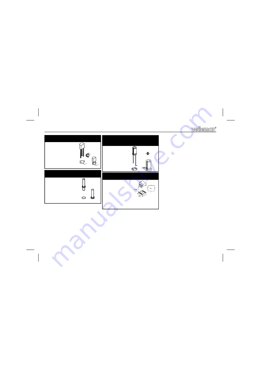
SW1
SW2
SW3
8. PCB pins
IC1 : SAE800
Pay attention to the position
of the notch!
10. IC mounting
T1 : BC337 or eq
7. Transistors
C4 :
10µ F
C5 :
470µ F
C6 :
9. Electrolytic Capacitors. Watch the polarity !
C...
Construction
Page 1: ...AL H6600IP 1 Total solder points 74 Difficulty level beginner 1 2 3 4 5 advanced This device is a simple and economic way of generating electronic tones This kit is primarily intended for use as a rep...
Page 2: ...rent push buttons Adjustable tone and volume control Peak output power 0 3W 8 Ohm speaker Power Supply 6 to 9VAC 0 2A or 4 5V battery 3 x 1 5V Standby current less than 10 A Dimensions WxDxH 53x59x25m...
Page 3: ...he eyes Needle nose pliers for bending leads or to hold components in place Small blade and Phillips screwdrivers A basic range is fine For some projects a basic multi meter is required or might be ha...
Page 4: ...e the solder joints are cone shaped and shiny 3 Trim excess leads as close as possible to the solder joint REMOVE THEM FROM THE TAPE ONE AT A TIME AXIAL COMPONENTS ARE TAPED IN THE CORRECT MOUNTING SE...
Page 5: ...IC socket Watch the po sition of the Construction RV1 22K RV2 22K 6 Trim potentiometers RV1 D1 1N4148 D2 1N4148 D3 1N4007 D4 1N4007 2 Diodes Watch the polarity D CATHODE D5 1N4007 D6 1N4007 D7 1N4007...
Page 6: ...SW1 SW2 SW3 8 PCB pins IC1 SAE800 Pay attention to the position of the notch 10 IC mounting T1 BC337 or eq 7 Transistors C4 10 F C5 470 F C6 470 F 9 Electrolytic Capacitors Watch the polarity C Const...
Page 7: ...7 11 Connection of battery as supply Connection...
Page 8: ...8 12 Connection of transformer as supply Connection...
Page 9: ...9 13 Connecting a transformer and backup battery supply Connection...
Page 10: ...10 14 Schematic diagram Schematic diagram...
Page 11: ...11 15 PCB PCB...
Page 12: ...ions and typographical errors reserved Velleman Components nv H6600IP 2007 ED1 VELLEMAN Components NV Legen Heirweg 33 9890 Gavere Belgium Europe www velleman be www velleman kit com 5 4 1 0 3 2 9 2 8...