


CAMCOLD1
- 4 -
VELLEMAN
a.
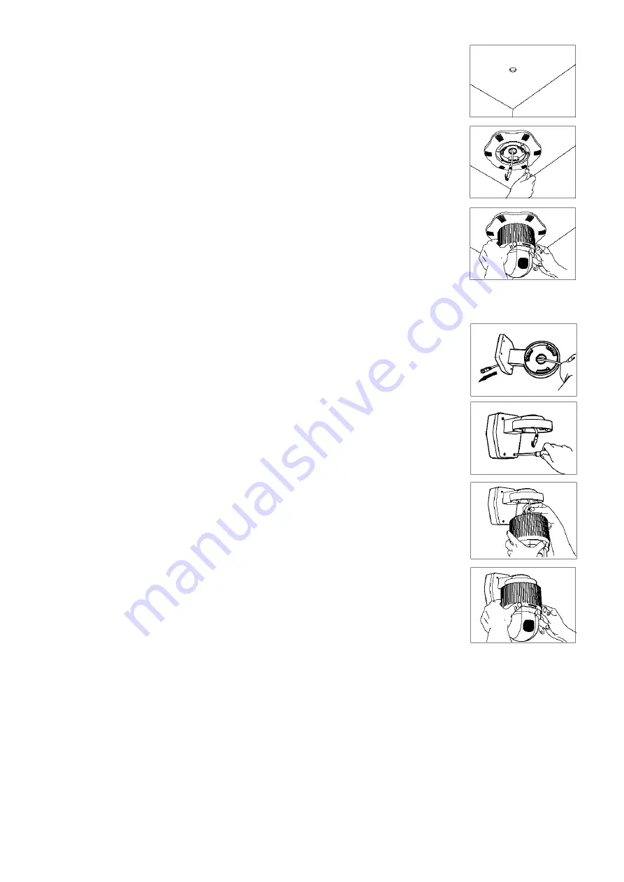
Ceiling Mounting
1.
Choose a mounting location. Drill a Ø30mm hole for the cabling in the ceiling using an
appropriate hole saw. If the ceiling isn’t firm enough, install a suitable board to
strengthen. Now, install the mounting bracket for dome cameras (
CAMCOLD/CB
).
2.
Connect the 8-core twisted pair to the RS485 adapter and slide it through the hole in
the ceiling. Connect the other end of the cable to the dome camera. For the correct
wiring of the RS485 adapter, refer to “
Connection
”.
3.
Place the dome onto the mounting bracket. Align the three tabs on the dome camera
with the three slots on the mounting bracket. Push and turn the camera in a clockwise
direction until it locks in place.
b.
Wall Mounting
REMARK:
To avoid vibrating pictures, make sure the construction to which the device is attached is able to support
5 times the weight of the camera and the bracket.
1.
Open the back of the wall bracket (
CAMCOLD/B1
) and slide the cable through the
hole.
2.
Connect the cable to the RS485 adapter. Mount the wall bracket onto the wall and fix it
using the screws included with the wall bracket.
3.
Connect the twisted pair to the dome camera. Place the camera onto the wall bracket.
Align the three tabs on the camera with the three slots of the bracket. Push and turn the
camera in a clockwise direction until it locks in place.
8. Controlling the Dome Camera
a.
Selecting the Camera
•
Choose a camera by pressing the camera number 1 – 99 and the CAM key.
•
Press -1 to choose the previous camera or press +1 to choose the next camera.
Example: Selecting camera n° 2.
o
Press 2 and the CAM key to select camera n° 2.
o
After having selected the camera, press -1 to select the previous camera or press +1 to select the next
camera.
b.
Controlling the P/T and the Lens
•
Select a camera (see “
Selecting a Camera
”).
•
Press Z-, Z+, F- or F+ to control the P/T or tilt the joystick to control the lens.


