5 / 43
3. INSTALLATION
This section contains detailed instructions for installing the camera. These instructions assume that the installer has a
good knowledge of installation techniques and is capable of adopting safe installation methods.
3.1. DIP SWITCH SETTING
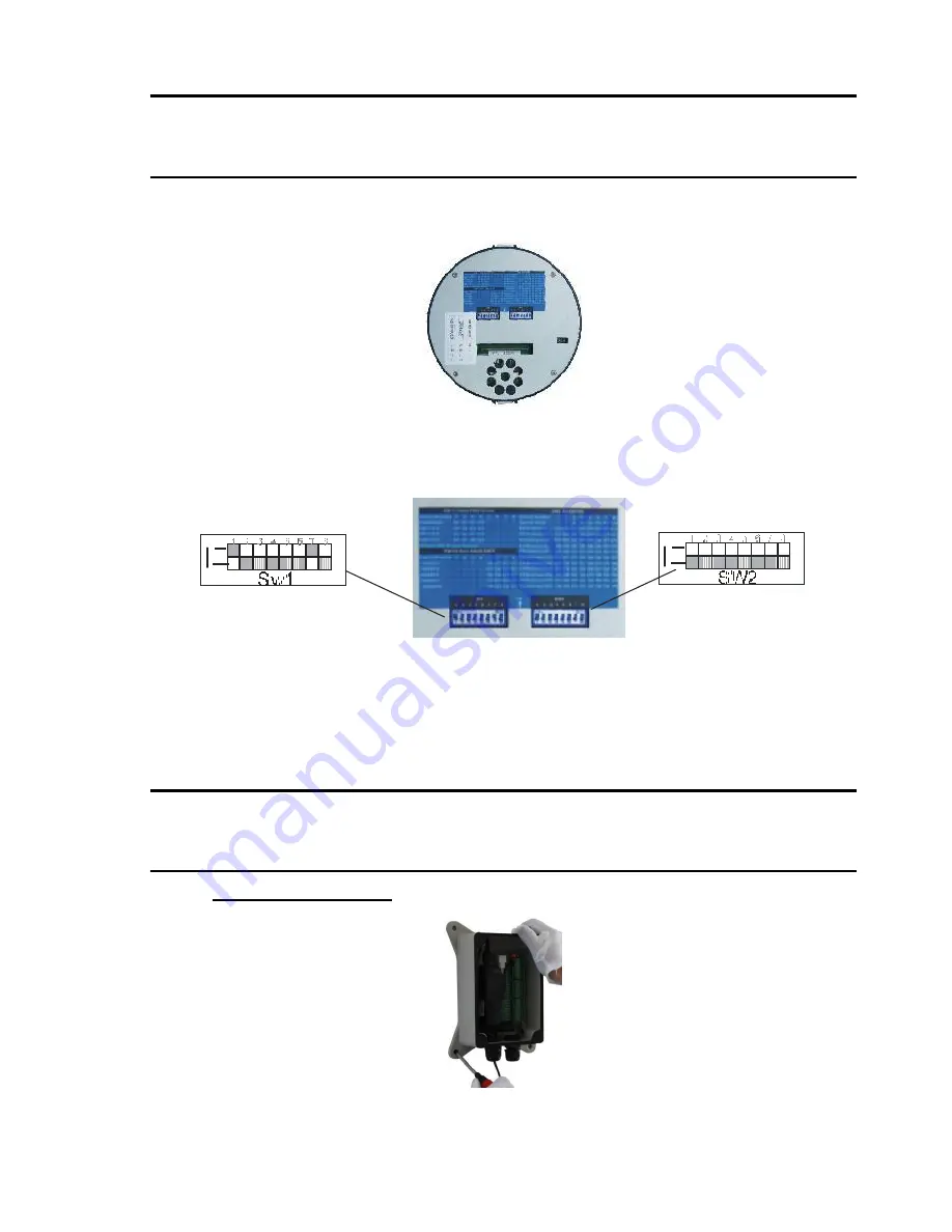
Before installing the camera drive, check the DIP switches; configure the receiver address, communication protocol, and
baud rate setting. Pic. 1 shows switches position and default settings. SW1 switches (1bit) and SW2 switches (1, 2, and 7
bit) are set to the ON position. For normal user, setting switches to default position is enough.
Pic. 1 Switch Position
The camera can be controlled via various communication protocols by setting SW1 switches(1, 2, 3,and 4) and operate at
1200bps, 2400bps, 4800bps, 9600bps and 19200bps baud rate by setting SW1 switches(5, 6, 7, and 8). Do not set the
switches to reserved position. Pic. 2 shows the default settings for the DIP switches.
Pic. 2 Default settings of DIP switches
Please refer to
Table 28: SWITCH1 SETTING
and
Table 29: SWITCH2 SETTING
in
Section 6.1
to set baud rate, and
communication protocol type and camera address.
Always use the
“PELCO P” or “PELCO D” protocols.
Do not use address
“0” with the “PELCO P” or “PELCO D” protocols.
3.2. INSTALLATION
The camera has four types of mountings: wall mount, in-ceiling mount, surface mount, and pole mount. Please make sure
which type you are installing.
3.2.1. WALL MOUNT INSTALLATION (WITH POWER BOX)
Step 1.
Install the power box on wall
Pic. 3
Install the power box to the wall with 4 screws.
When installing outdoors, make sure installation is properly sealed to keep moisture out.


